Optical lens

a technology of optical lenses and lenses, applied in the field of optical imaging, can solve the problems of increased lens cost, limited field of view of lenses, and difficult observation of larger angle ranges around vehicles

Active Publication Date: 2019-10-31
NINGBO SUNNY AUTOMOTIVE OPTECH
View PDF0 Cites 14 Cited by
  • Summary
  • Abstract
  • Description
  • Claims
  • Application Information

AI Technical Summary

Benefits of technology

[0006]An advantage of the present disclosure is to provide an optical lens, wherein the optical lens has a longer focal length and a larger viewing distance in a smaller range of field of view near its center.
[0007]An advantage of the present disclosure is to provide an optical lens, wherein the optical lens has a larger overall field of view and a wide viewing range.
[0008]An advantage of the present disclosure is to provide an optical lens, wherein the optical lens has higher resolution.
[0010]An advantage of the present disclosure is to provide an optical lens, wherein the optical lens is suitable for an in-vehicle environment, and both telephoto and wide-angle functions can be simultaneously realized by one lens, thereby reducing the lens cost of the driving system.
[0011]An advantage of the present disclosure is to provide an optical lens, wherein the optical lens has a central region of high angular resolution and high environmental recognition.
[0027]According to some embodiments, in the optical lens, the fourth lens has an object surface and an image surface, the object surface of the fourth lens faces the object side, the image surface of the fourth lens faces the image side, the object surface of the fourth lens is convex, the image surface of the fourth lens is convex, the fifth lens has an object surface and an image surface, the object surface of the fifth lens faces the object side, the image surface of the fifth lens faces the image side, the object surface of the fifth lens is concave, the image surface of the fifth lens is convex, the sixth lens has an object surface and an image surface, the object surface of the sixth lens faces the object side, the image surface of the sixth lens faces the image side, the object surface of the sixth lens is convex, the image surface of the sixth lens is convex, and the sixth lens has a positive focal power.

Problems solved by technology

However, this makes the field of view of the lens to be limited, and the field of view is smaller so that a larger angle range around the vehicle is difficult to be observed.
However, the entire driving assistance system needs to use two or more optical lenses to cooperate with each other, so that the cost of the lenses increases and the space occupied by the lenses in the vehicle body increases.

Method used


Image

  • Optical lens
  • Optical lens
  • Optical lens

Examples


first embodiment

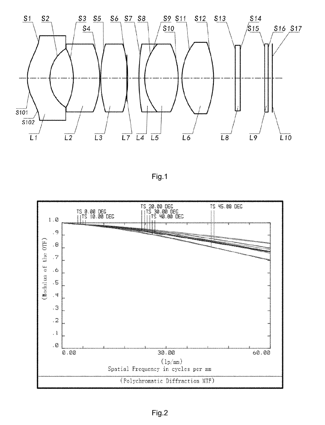
[0062]Referring to FIGS. 1 and 2 of the accompanying drawings, an optical lens according to the present disclosure is explained, wherein the optical lens includes at least one first lens L1, at least one second lens L2, a third lens L3, a fourth lens L4, a fifth lens L5 and a sixth lens L6. The first lens L1, the second lens L2, the third lens L3, the fourth lens L4, the fifth lens L5, and the sixth lens L6 are sequentially arranged along a direction from an object side to an image side.

[0063]The first lens L1 has a negative focal power, and the first lens L1 has an object surface S1 facing the object side and an image surface S2 facing the image side. According to this embodiment of the present disclosure, the object surface S1 of the first lens L1 is convex in order to increase the luminous flux of the optical lens. That is, the convex object surface S1 of the first lens L1 converges light at a larger angle to increase the luminous flux entering the optical lens from the object si...

second embodiment

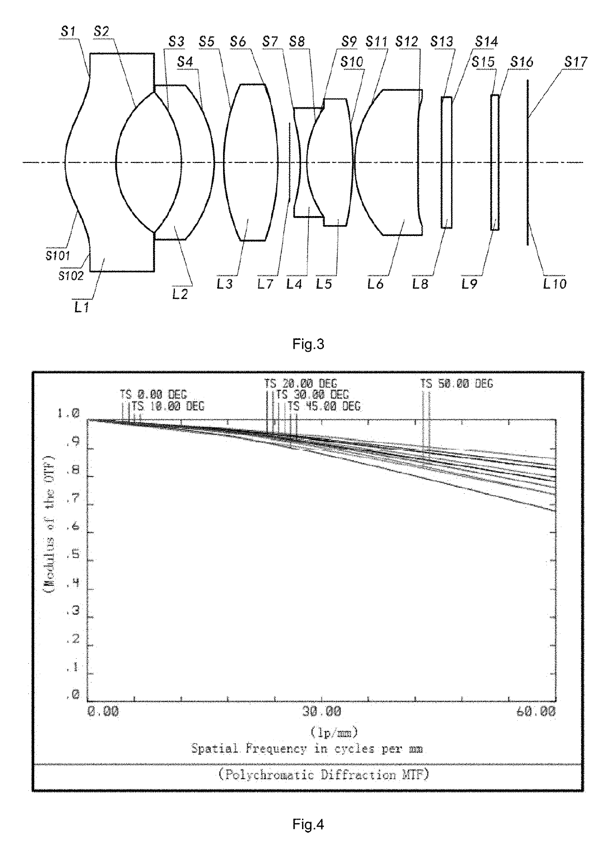
[0107]Referring to FIGS. 3 and 4, an optical lens according to the present disclosure is explained, wherein the optical lens includes at least one first lens L1, at least one second lens L2, a third lens L3, a fourth lens L4, a fifth lens L5 and a sixth lens L6. The first lens L1, the second lens L2, the third lens L3, the fourth lens L4, the fifth lens L5, and the sixth lens L6 are sequentially arranged along a direction from an object side to an image side.

[0108]The first lens L1 has a negative focal power, and the first lens L1 has an object surface S1 facing the object side and an image surface S2 facing the image side. According to this embodiment of the disclosure, the object surface S1 of the first lens L1 is convex in order to increase the luminous flux of the optical lens. That is, the convex object surface S1 of the first lens L1 converges light at a large angle to increase the luminous flux entering the optical lens from the object side. Preferably, the object surface S1 ...

third embodiment

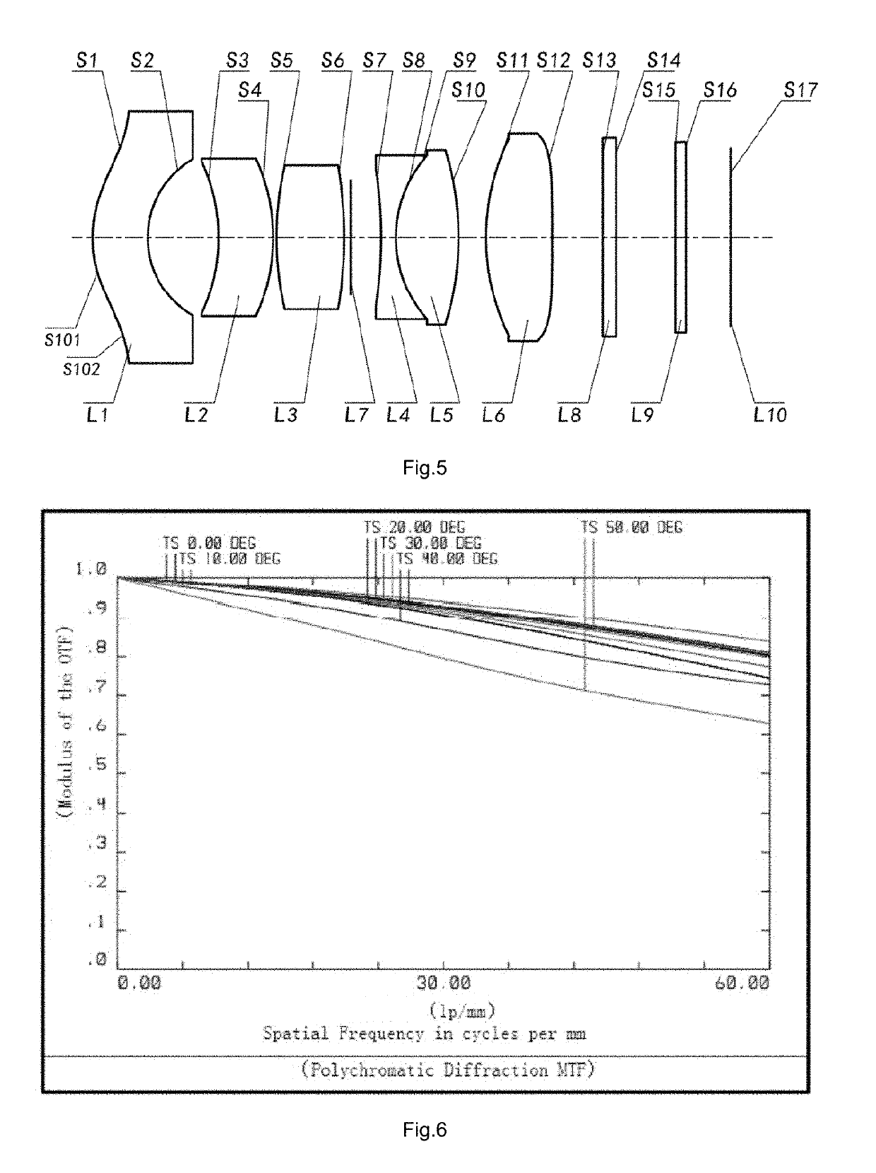
[0152]Referring to FIGS. 5 and 6, an optical lens according to the present disclosure is explained, wherein the optical lens includes at least one first lens L1, at least one second lens L2, a third lens L3, a fourth lens L4, a fifth lens L5 and a sixth lens L6. The first lens L1, the second lens L2, the third lens L3, the fourth lens L4, the fifth lens L5, and the sixth lens L6 are sequentially arranged along a direction from an object side to an image side.

[0153]The first lens L1 has a negative focal power, and the first lens L1 has an object surface S1 facing the object side and an image surface S2 facing the image side. According to this embodiment of the present disclosure, the object surface S1 of the first lens L1 is convex in order to increase the luminous flux of the optical lens. That is, the convex object surface S1 of the first lens L1 converges light at a larger angle to increase the luminous flux entering the optical lens from the object side. Preferably, the object su...


PUM


Abstract

An optical lens comprises: a first lens having a negative focal power; a second lens; a third lens; a fourth lens; a fifth lens, wherein the fourth lens and the fifth lens forms an achromatic lens group; and a sixth lens, wherein the first lens, the second lens, the third lens, the fourth lens, the fifth lens, and the sixth lens are sequentially disposed along a direction from an object side to an image side, wherein the first lens has at least one object surface facing the object side, and the object surface of the first lens is convex, and wherein the second lens has at least one image surface facing the image side, and the image surface of the second lens is convex so as to facilitate forming a concentric circle structure.

Description

TECHNICAL FIELD[0001]The present disclosure relates to the technical field of optical imaging, and more particularly relates to an optical lens for optical imaging.TECHNICAL BACKGROUND[0002]In recent years, with the development of electronic technology, the application range of the cameras is becoming wider and wider. In-vehicle cameras are one of the important aspects, and optical lenses are an important component in the in-vehicle cameras.[0003]At present, a conventional car camera has different functions due to different installation positions. For example, a front-view camera usually needs to observe distant objects, and thus the focal length of the optical lens is required to be longer. However, this makes the field of view of the lens to be limited, and the field of view is smaller so that a larger angle range around the vehicle is difficult to be observed. In order to enable the environmental conditions within the larger angle range around the vehicle to be observed at the sa...

Claims


Application Information

Patent Timeline
Patent Type & Authority Applications(United States)
IPC IPC(8): G02B13/00G02B13/02
CPCG02B13/0045G02B13/0055G02B13/02G02B15/177G02B13/0015G02B13/006G02B13/06G02B9/62
Inventor YAO, BOXIE, QIANSENWANG, DONGFANG
Owner NINGBO SUNNY AUTOMOTIVE OPTECH
Why Eureka
Try Eureka