
Image processing apparatus, image processing method, and storage medium

Active Publication Date: 2019-10-31
CANON KK
View PDF0 Cites 4 Cited by
  • Summary
  • Abstract
  • Description
  • Claims
  • Application Information

AI Technical Summary

Benefits of technology

The invention allows for adjusting the weights of pixel values in a difference image using the pixel values from multiple images. This reduces the need for a user to manually select a reference image to adjust the weights, which can save time for a doctor or other user.

Problems solved by technology

In the difference image, a region other than a region of interest of a doctor on the difference image may be depicted due to a difference in imaging condition between the reference image and the deformation target image or a change in condition of the object, thereby deteriorating the visibility of the region of interest.
Therefore, even in a region of non-interest of the doctor on the difference image, a change is depicted on the image, thereby deteriorating the visibility of the difference values in the region of interest of the doctor.

Method used


Image

  • Image processing apparatus, image processing method, and storage medium
  • Image processing apparatus, image processing method, and storage medium
  • Image processing apparatus, image processing method, and storage medium

Examples


first embodiment

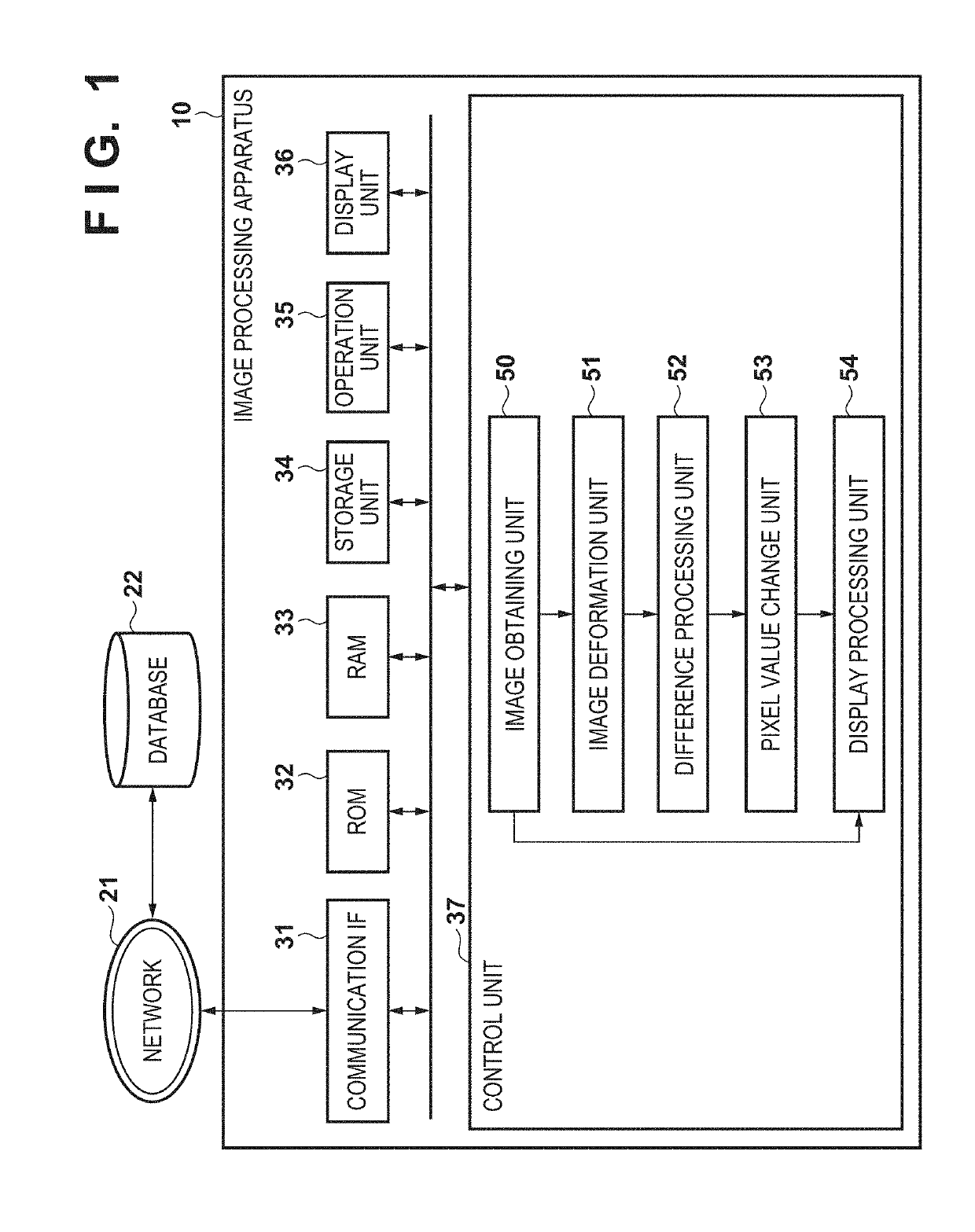
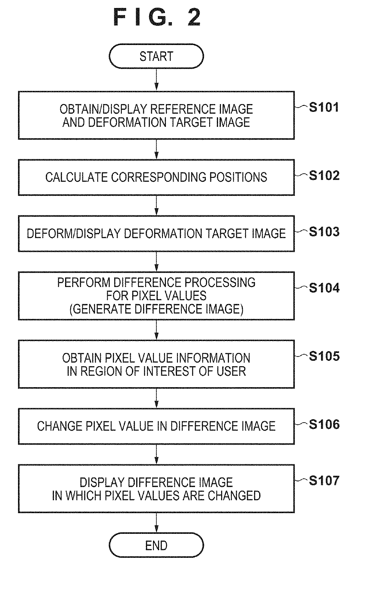
[0027]An image processing apparatus according to the first embodiment obtains a difference image between a plurality of images (a reference image and a deformation target image), and executes image processing for appropriately adjusting the weights of pixel values on the difference image. The image processing apparatus is characterized by, during a process of obtaining the difference image and executing the image processing, obtaining, from a pixel value in the reference image and that in the deformation target image having undergone deformable registration with the reference image, an index (likelihood) of being a pixel included in a region of interest of the user such as a doctor, and using the obtained index (likelihood) as a weight for the difference value.

[0028]In this technique, for example, it is possible to improve the visibility of difference values in a region of interest of the user by setting weights for pixels included in the region of interest larger than those for pix...

second embodiment

[0103](Pixels Outside a Region of Interest are Extracted, and Used to Change Pixel Values in a Difference Result.)

[0104]In the first embodiment, the pixel value change unit changes the pixel values in the difference result using the distribution of the pixel values in the region of interest, the result of extracting the pixels in the region of interest, and the like. To the contrary, the pixel values in the difference result may be changed using the distribution of pixel values outside the region of interest and the extraction result.

[0105]This embodiment will explain, for example, a case in which if a bone is set as a region of interest, information in which a region such as a heart or liver outside the region of interest is extracted or enhanced is obtained and pixel values in a difference result are changed based on the information.

[0106]The arrangement of an image processing apparatus according to the second embodiment is the same as that according to the first embodiment except...


PUM


Abstract

An image processing apparatus includes: an obtaining unit configured to obtain a first image of an object and a second image of the object; a difference unit configured to obtain a difference image after the first image and the second image are registered; and a change unit configured to perform processing of changing a pixel value in the difference image based on a likelihood calculated using a pixel value in the first image and a pixel value in the second image.

Description

BACKGROUND OF THE INVENTIONField of the Invention[0001]The present invention relates to an image processing apparatus, an image processing method, and a storage medium.Description of the Related Art[0002]In the medical field, diagnosis is performed using images obtained by various types of medical imaging apparatuses (modalities) such as a computed tomography apparatus (to be referred to as a CT (Computed Tomography) apparatus hereinafter). Especially, to capture a change in condition of an object with time, images obtained at different timings are compared. One of images to be compared will be referred to as a reference image hereinafter, and the other image will be referred to as a deformation target image hereinafter.[0003]As image processing of visualizing a change with time between the reference image and the deformation target image, there is known a technique of obtaining an image (to be referred to as a difference image hereinafter) representing the difference between the im...

Claims


Application Information

Patent Timeline
IPC IPC(8): G06T7/00G06T7/254G06T7/33G06T5/50
CPCG06T2207/30061G06T5/50G06T2207/30056G06T7/0016G06T2207/20216G06T2207/30008G06T7/337G06T7/254G06T2207/20224G06T2207/10081G06T2200/24G06T7/30G06T11/003G06T2207/10116G06T2207/20221
Inventor NAKAGOMI, KEITA
Owner CANON KK
Learn More