

Work vehicle and method of controlling work vehicle
- Summary
- Abstract
- Description
- Claims
- Application Information
AI Technical Summary
Benefits of technology
Problems solved by technology
Method used
Image

Examples
Embodiment Construction
[0017]A work vehicle according to an embodiment of the present disclosure will be described below with reference to the drawings. The same elements have the same reference characters allotted in the description below and their labels and functions are also the same. Therefore, detailed description thereof will not be repeated.
[0018]A construction of a motor grader representing one example of a work vehicle to which the concept of the present disclosure is applicable will initially be described.
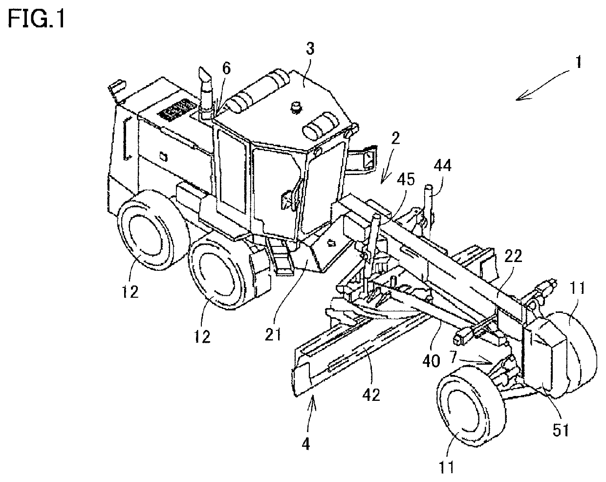
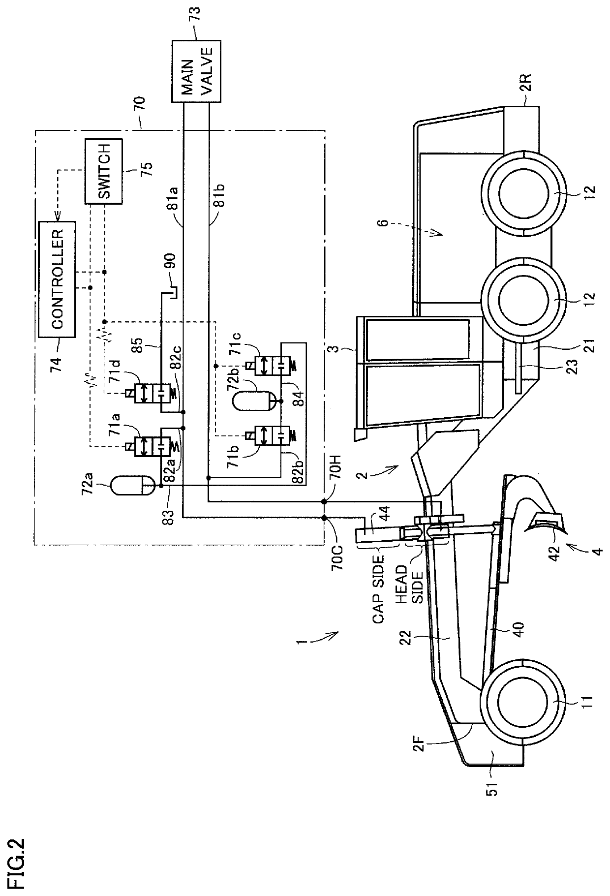
[0019]FIG. 1 is a perspective view schematically showing a construction of a motor grader in one embodiment of the present disclosure. FIG. 2 is a side view schematically showing the construction of the motor grader in one embodiment of the present disclosure.
[0020]As shown in FIGS. 1 and 2, a motor grader 1 in the present embodiment mainly includes running wheels 11 and 12, a vehicular body frame 2, a cab 3, and a work implement 4. Motor grader 1 includes components such as an engine arranged...
PUM
 Abstract
Description
Claims
Application Information