Engine control device and engine control method

Active Publication Date: 2016-11-10
TOYOTA JIDOSHA KK
View PDF16 Cites 2 Cited by
  • Summary
  • Abstract
  • Description
  • Claims
  • Application Information

AI Technical Summary

Benefits of technology

[0018]In the control device as described above, the electronic control unit may be configured to maintain the ignition timing at the start point of the ignition timing retard control for a predetermined period, after the start of the ignition timing retard control, and reduce the predetermined period when the elapsed period from the malfunction diagnosis of the exhaust gas recirculation system to the return from the fuel cutoff is equal to or less than the criterial value, to be shorter than the predetermined period in the case where the elapsed period is longer than the criterial value. With this arrangement, the engine torque rises early after the engine returns from the fuel cutoff state. Therefore, even if the timing of release of torsional strain is advanced, the engine torque can be raised or increased before the swing-over occurs, and the vibrations of the vehicle body can be favorably suppressed.
[0019]In the control device as described above, the electronic control unit may be configured to maintain the ignition timing at the start point of the ignition timing retard control for a predetermined period, after the start of the ignition timing retard control, and then advance the ignition timing until the ignition timing is returned to a base ignition timing, such that a rate at which the ignition timing is advanced is higher when the elapsed period from the malfunction diagnosis of the exhaust gas recirculation system to the return from the fuel cutoff is equal to or less than the criterial value, than the ignition timing in the case where the elapsed period is longer than the criterial value. In this case too, the engine torque is raised from an earlier point in time, and the vehicle body vibrations can be favorably suppressed.
[0020]In order to recover the exhaust cleanup capability of a catalyst, which has deteriorated during fuel cutoff, the air-fuel ratio may be temporarily shifted to the rich side when the engine returns from the fuel cutoff state. In this case, if the air-fuel ratio is switched to a leaner value after being temporarily shifted to the rich side, the e

Problems solved by technology

If the engine returns from the fuel cutoff state at this time, combustion is resumed in a condition where air containing combustion gas is introduced in the cylinder, which may result in unstable combustion.
If the ignition timing is not retarded at the initial explosion after the return, as

Method used


Image

  • Engine control device and engine control method
  • Engine control device and engine control method
  • Engine control device and engine control method

Examples


Example

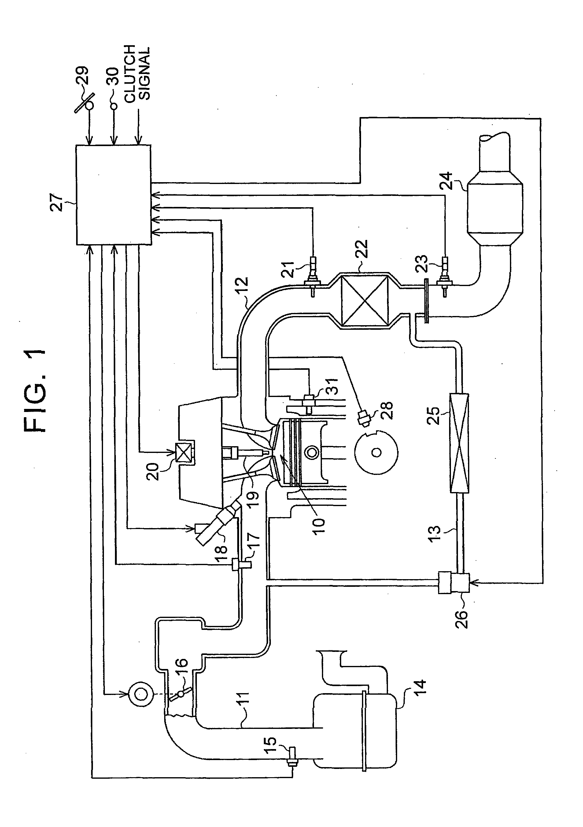
[0031]Referring to FIG. 1 through FIG. 6, an engine control device as one embodiment of the invention will be described in detail. In FIG. 1, the configuration of an engine in which the control device of this embodiment is employed is illustrated. As shown in FIG. 1, the engine has an intake passage 11 through which intake air to be fed to a combustion chamber 10 flows, and an exhaust passage 12 through which exhaust gas discharged from the combustion chamber 10 flows.

[0032]In the intake passage 11, an air cleaner 14, air flow meter 15, throttle valve 16, intake pressure sensor 17, and an injector 18 are installed in this order as seen from the upstream side of the passage 11. The air cleaner 14 filters out dust, etc. in the atmosphere drawn into the intake passage 11, so as to clean the intake air. The air flow meter 15 detects the amount (intake air amount GA) of new air thus drawn into the intake passage 11. The throttle valve 16 adjusts the intake air amount GA by changing the d...


PUM


Abstract

A control device for an engine including an EGR system, the control device includes an electronic control unit. The electronic control unit is configured to forcedly open and close an EGR valve and make a malfunction diagnosis of the EGR system, during fuel cutoff, perform ignition timing retard control when the engine returns from the fuel cutoff, and set the ignition timing at a start point of the ignition timing retard control to a more advanced value when an elapsed period from the malfunction diagnosis of the EGR system to a return from the fuel cutoff is short, as compared with the case where the elapsed period is long, so as to reduce a retard amount of the ignition timing at the start point of the ignition timing retard control, relative to the ignition timing immediately before the start of the ignition timing retard control.

Description

BACKGROUND OF THE INVENTION[0001]1. Field of the Invention[0002]The invention relates to an engine control device that makes a malfunction diagnosis of an exhaust gas recirculation system during fuel cutoff, and also relates to an engine control method.[0003]2. Description of Related Art[0004]An exhaust gas recirculation (EGR) system that recirculates a part of exhaust gas into intake air is known as a system installed on a vehicle, or the like. The EGR system has an EGR passage that connects an exhaust passage and an intake passage of the engine, and an EGR valve mounted in the EGR passage. The EGR system is configured to increase and reduce the EGR amount, i.e., the amount of gas recirculated from the exhaust passage into the intake passage, through control of the degree of opening of the EGR valve.[0005]In a system as described in Japanese Patent Application Publication No. 2009-257280 (JP 2009-257280 A), a malfunction diagnosis of the EGR system as described above is conducted d...

Claims


Application Information

Patent Timeline
IPC IPC(8): F02P5/04F02D41/00F02M26/53F02P5/145F02M26/49
CPCF02P5/045F02P5/145F02D41/0077F02M26/53F02M26/49F02D41/126F02D41/307F02P5/1516F02D37/02Y02T10/40
Inventor TANAKA, HIROYA
Owner TOYOTA JIDOSHA KK
Why Eureka
Try Eureka