Optical pickup and disk drive device

Inactive Publication Date: 2008-07-03
KK TOSHIBA
View PDF1 Cites 1 Cited by
  • Summary
  • Abstract
  • Description
  • Claims
  • Application Information

AI Technical Summary

Benefits of technology

[0013]According to the present invention, the optical pickup and the disk drive device capable of obtaining the good optical

Problems solved by technology

Therefore, the mechanical strength of the optical base as a whole is not necessarily sufficient, and hence the above stru

Method used


Image

  • Optical pickup and disk drive device
  • Optical pickup and disk drive device
  • Optical pickup and disk drive device

Examples


Example

First Embodiment

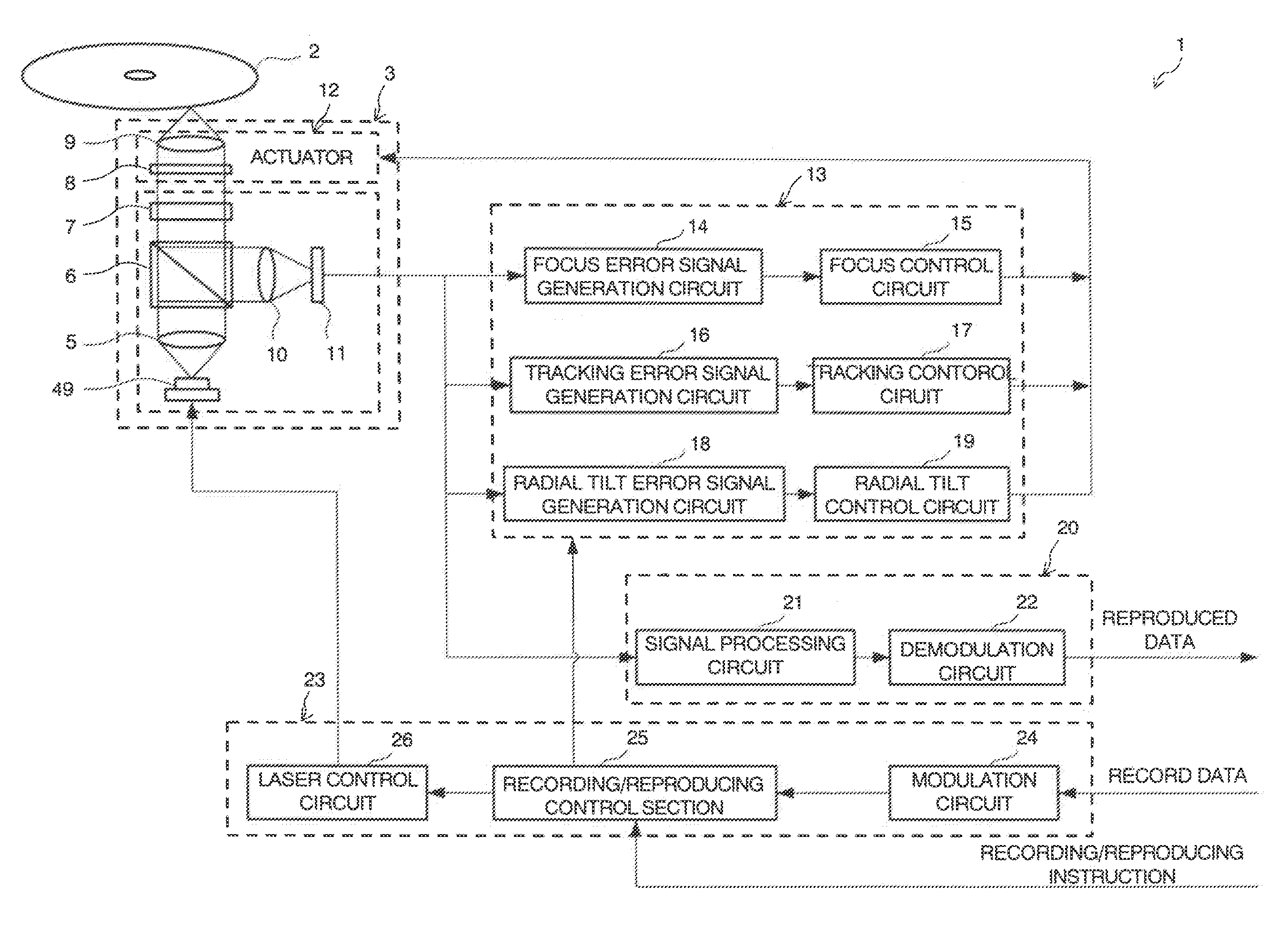
[0030]FIG. 1 is a functional block diagram showing a disk drive device 1 equipped with an optical pickup 3 according to a first embodiment of the present invention. Incidentally, in FIG. 1, an optical system in the optical pickup 3 is shown in a simplified manner.

[0031]First, mainly a control system of the disk drive device 1 of this embodiment will be described based on FIG. 1. The disk drive device 1 is an optical disk recording / reproducing device capable of recording and / or reproducing an optical disk 2 such as a CD (compact Disc), a DVD (Digital Versatile Dick), or an HD DVD (High Definition DVD), and as shown in FIG. 1, includes the optical pickup 3 being an optical head, a three-axis control section (three-axis drive control section) 13, a reproducing processing section 20, and a recording processing section 23.

[0032]As well as irradiating laser light to the optical disk 2 to record and reproduce information, the optical pickup 3 converts reflected light from t...

Example

Second Embodiment

[0061]Next, a second embodiment of the present invention will be described based on FIG. 13 and FIG. 14. Here, FIG. 13 is an exploded perspective view of an optical pickup 73 according to the second embodiment of the present invention, and FIG. 14 is an enlarged view of a peripheral portion of a beam 75c in a head base 75 of the optical pickup 73 seen from the bottom surface side of the optical pickup 73. Incidentally, in this embodiment, in FIG. 13 and FIG. 14 above, the same reference numerals and symbols will be used to designate the same components as those provided in the optical pickup 3 of the first embodiment shown in FIG. 8 and FIG. 9, and a detailed description thereof will be omitted.

[0062]Namely, in the head base 75 of the optical pickup 73 according to this embodiment, an opening 75a (second opening) into which an insert 7a provided in the rising mirror 7 is inserted is formed in the beam 75c. Further, the optical pickup 73 includes joints (second joint...


PUM


Abstract

Disclosed is an optical pickup including: an actuator supporting a lens holder holding an objective lens and a yoke base including a predetermined insert and holding a magnet for driving magnetically the lens holder; a head base having an opening into which the insert of the yoke base is inserted formed, and supporting the actuator in a state where the insert is inserted into the opening; and a joint joining an edge of the opening formed in the head base and the insert of the yoke base inserted into the opening to each other.

Description

CROSSREFERENCE TO RELATED APPLICATIONS[0001]This application is based upon and claims the benefit of priority from the prior Japanese Patent Application No. 2006-355147, filed on Dec. 28, 2006; the entire contents of which are incorporated herein by reference.BACKGROUND[0002]1. Field of the Invention[0003]The present invention relates to an optical pickup and a disk drive device to record and / or reproduce information using a disk medium such as an optical disk.[0004]2. Description of the Related Art[0005]With the recent spread of notebook PCs and transportable DVD reproducing apparatuses, optical disk drive devices mounted in these apparatuses and optical pickups embedded in these optical disk drive devices are required to be downsized and thinned.[0006]For example, the optical pickup can be thinned by inserting an objective lens drive unit and a rising mirror into an opening formed in an optical base to a bottom surface of the optical base and attaching these parts to each other in...

Claims


Application Information

Patent Timeline
IPC IPC(8): G11B7/00
CPCG11B7/0946G11B7/0933
Inventor KUROKAWA, KENYANAGASATO, MAKOTO
Owner KK TOSHIBA
Why Eureka
Try Eureka