

Plastic optical element and method of manufacturing the same
- Summary
- Abstract
- Description
- Claims
- Application Information
AI Technical Summary
Benefits of technology
Problems solved by technology
Method used
Image

Examples
first embodiment
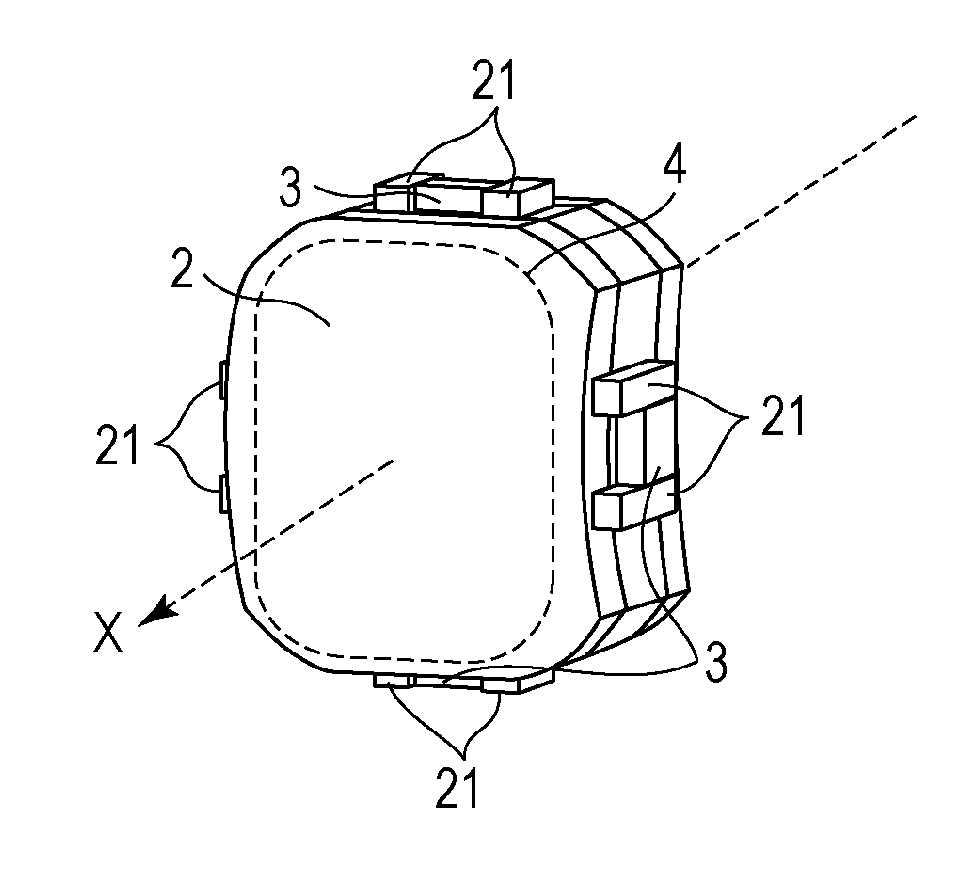
[0018]A plastic optical element according to a first embodiment of the present invention will be described below.
[0019]The plastic optical element according to the first embodiment includes a member and covering portions formed on a first surface and a second surface of the member. The member includes a projecting portion made of a material out of which the member is made and a material out of which the covering portions are made on a part of the side surface of the member, and the covering portion of the first surface and the covering portion of the second surface are connected to each other through the projecting portion. A transparent member that is to be a core of the plastic optical element (a lens) after the covering portions are formed on the surfaces thereof will be referred to herein as a member. In other words, a member that is a center core (a core) of the plastic optical element (a lens) will be referred to herein as a member. The member may be a lens. The surfaces of th...
second embodiment
[0033]A plastic optical element according to a second embodiment of the present invention will now be described below.
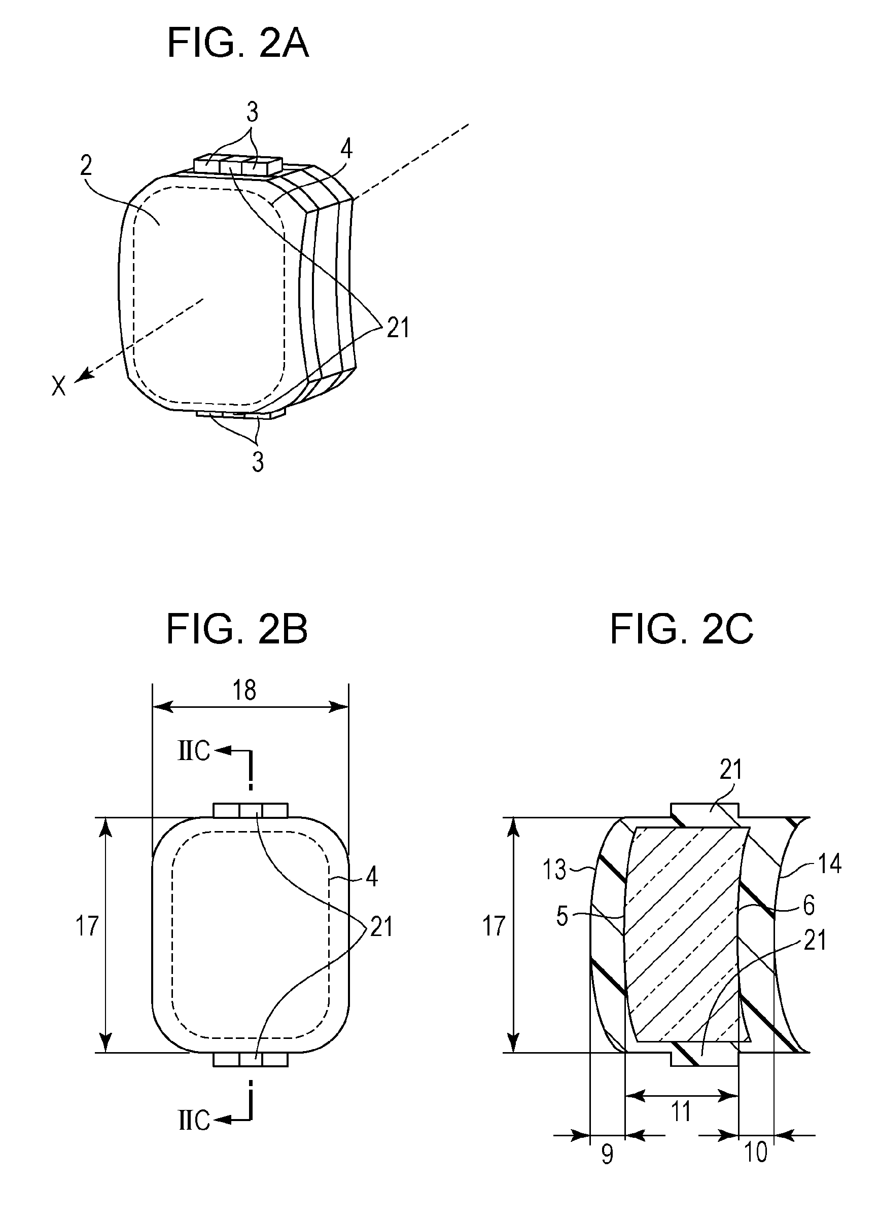
[0034]FIG. 5A, FIG. 5B, and FIG. 5C are a perspective view, a plan view, and a sectional view of a member according to the second embodiment, respectively. FIG. 6A, FIG. 6B, and FIG. 6C are a perspective view, a plan view, and a sectional view of the plastic optical element according to the second embodiment, respectively. The same elements as in FIGS. 1A to 1C and FIGS. 2A to 2C are denoted by the same reference numerals, and repeated descriptions thereof will be omitted.
[0035]FIGS. 5A to 5C illustrate the shape of a member 1. FIGS. 5A to 5C illustrate an example in which the member 1 has a quadrangular shape with rounded corners and in which a protruding portion 3 is formed at four positions that are on the outer surface of the member and that are in the center portions of the short sides and the long sides of the member. Forming the protruding portion 3 at four po...
example 1
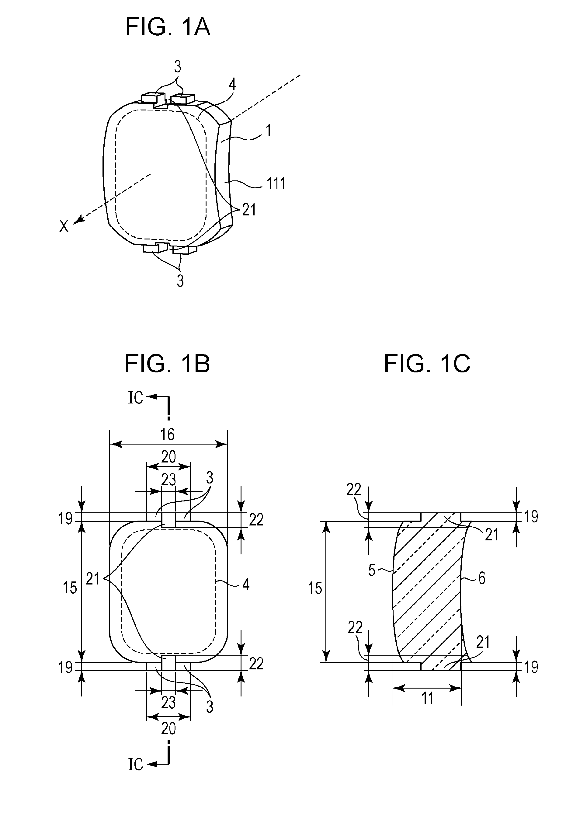
[0038]An injection mold 30 having a cavity for molding a member was prepared. The shape of the member to be molded was the same as that illustrated in FIGS. 1A to 1C. The member was a meniscus lens having a quadrangular shape with rounded corners and having an optically effective area 4 therein. The member had a height 15 of 18 mm, a width 16 of 15 mm, and a thickness 11 of 6 mm. Protruding portions 3 were formed at positions that are on the outer surface of the member and that are in the center portions of the short sides of the member, and the protruding portions 3 had a height 19 of 1 mm and a width 20 of 6 mm. The protruding portions 3 were symmetrically positioned in the top-bottom direction of the member. A connecting area 21 in which a first covering portion and a second covering portion were to be connected to each other when a plastic optical element was molded was formed in the center of each of the protruding portions 3. Each of the connecting areas 21 had a height 22 of ...
PUM
 Abstract
Description
Claims
Application Information