
Vibration control device and control method therefor

Active Publication Date: 2014-08-14
NAGASAKI UNIVERSITY +1
View PDF1 Cites 2 Cited by
  • Summary
  • Abstract
  • Description
  • Claims
  • Application Information

AI Technical Summary

Benefits of technology

The present invention provides a vibration control device that can automatically suppress vibration of a vibrating body without installing a vibration detection sensor or controlling its rotational speed or phase. The device is low-cost and can be used on various types of machines.

Problems solved by technology

However, since there is a limit to balancing of the rotary machine, an external force of a centrifugal force type is generated during an operation, and vibration occurs.
Furthermore, there are also machines which inevitably generate large imbalance during its operation due to its performances as in the case of an electric washing machine and reciprocating machines which inevitably generate vibration to some degree due to its structure as in the case of an engine.
However, the above-mentioned automatic balancer and the vibration compensator have some problems.
First, the automatic balancer has a problem in which it amplifies an amplitude of the machine in a region with a vibration frequency (frequency) lower than a resonant frequency (or a resonance point).
Second, the automatic balancer has a problem in which self-excited vibration is generated in a region of a vibration frequency higher than the resonance point.
That is, although the automatic balancer has a function of automatically suppressing vibration, the balance modifier and the like cannot be positively controlled, and thus vibration of the machine might be amplified in some cases.
Third, the vibration compensator requires a precise motor or a complicated control mechanism, and thus has a problem of a high cost.

Method used


Image

  • Vibration control device and control method therefor
  • Vibration control device and control method therefor
  • Vibration control device and control method therefor

Examples


Embodiment Construction

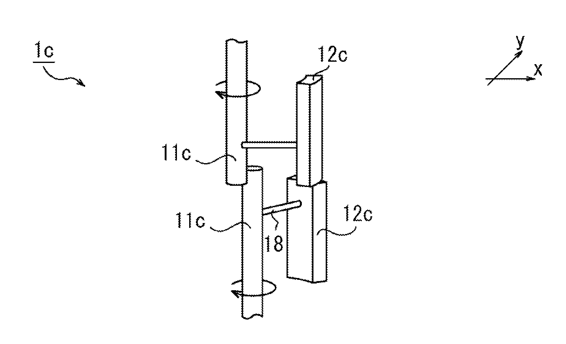
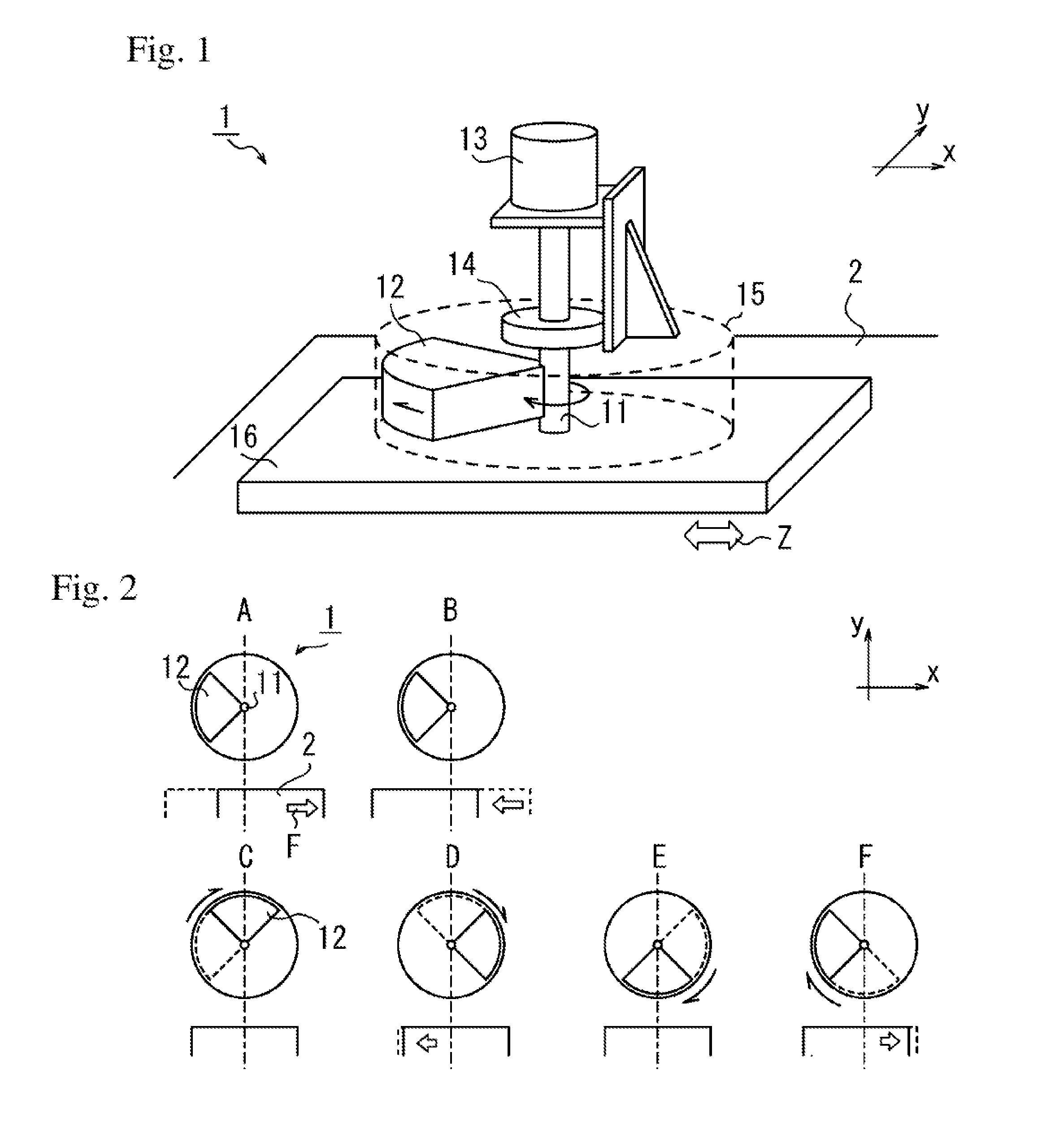
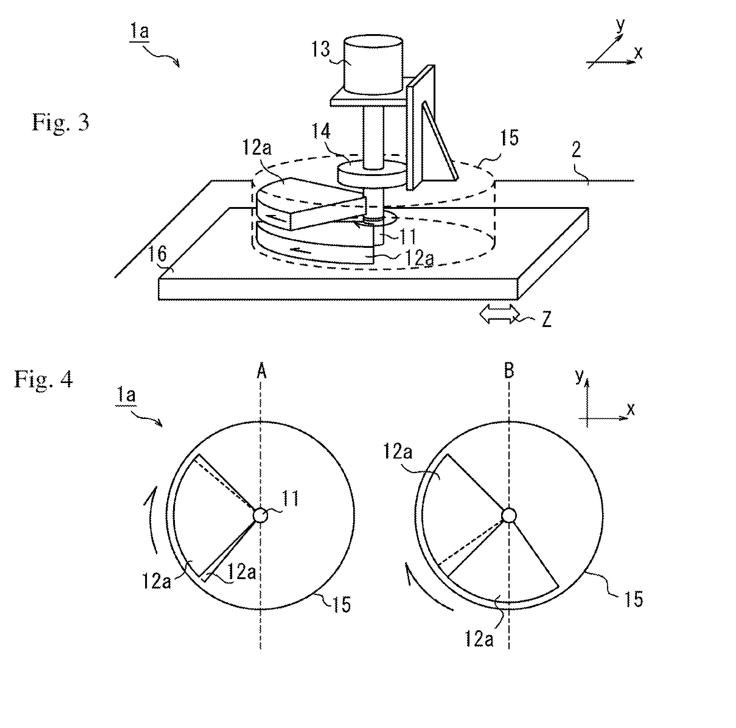
[0026]Hereinafter, a vibration control device of an embodiment according to the present invention will be described by referring to the attached drawings. Particularly, the vibration control device installed in a diesel engine for ships (hereinafter referred to as a vibrating body) will be described as an example. FIG. 1 illustrates an outline of the vibration control device 1 of the embodiment according to the present invention. The vibration control device 1 has a rotating shaft 11, a mass body 12 fixed to the rotating shaft 11, a casing 15 for protecting the mass body 12, a clutch 14 installed on the rotating shaft 11, and an activation apparatus (an electric motor, for example) 13 for start-up of the mass body 12 via the clutch 14. Furthermore, the vibration control device 1 has a bottom plate 16 and is installed on the vibrating body (a diesel engine, for example) 2 via this bottom plate 16. The mass body 12 is formed into a thick fan shape (hereinafter referred to as a disk-sh...


PUM


Abstract

Provided is a vibration control device, which enables the vibrations of a vibrating body, such as a rotary machine, to automatically be suppressed, without installing a vibration detection sensor on the vibration control device or vibrating body, and without controlling the rotational speed or phase of the vibration control device. The vibration control device (1), which is installed on a vibrating body (2) and controls the vibrations of the vibrating body (2), comprises a rotating shaft (11), a mass body (12) that is fixed to the rotating shaft (11), and an activation apparatus (13) that adds the power of a rotational motion, which is centered on the rotating shaft (11), to the mass body (12).

Description

TECHNICAL FIELD[0001]The present invention relates to a vibration control device mounted on a vibrating body and suppressing its vibration and a control method therefor.BACKGROUND ART[0002]A rotary machine such as a hard disk of a personal computer, an electric fan, a cutting device, and a power generation turbine is preferably designed with its imbalance as small as possible, and careful balancing is performed before shipment. However, since there is a limit to balancing of the rotary machine, an external force of a centrifugal force type is generated during an operation, and vibration occurs. Furthermore, there are also machines which inevitably generate large imbalance during its operation due to its performances as in the case of an electric washing machine and reciprocating machines which inevitably generate vibration to some degree due to its structure as in the case of an engine. In order to suppress vibration of these machines (hereinafter referred to as a vibrating body), a...

Claims


Application Information

Patent Timeline
IPC IPC(8): G05D19/02
CPCG05D19/02F16F7/1011F16F7/1022
Inventor YOSHITAKE, YUTAKAKAJIWARA, SHUHEI
Owner NAGASAKI UNIVERSITY
Learn More