Field apparatus for a rotary electric machine and field coil used for the field apparatus

Inactive Publication Date: 2006-10-05
DENSO CORP
View PDF2 Cites 1 Cited by
  • Summary
  • Abstract
  • Description
  • Claims
  • Application Information

AI Technical Summary

Benefits of technology

[0009] An object of the present invention is to provide, with due consideration to the drawbacks of the conventional field apparatus, a field apparatus manufactu

Problems solved by technology

Therefore, productivity of the apparatus is lowered, and the configuration of a manufacturing device for the apparatus is undesirably complicated.
The complicated configuration brings low reliability in the manufacturing of the apparatus.
However, because the cylindrical field coil having an opened inside space

Method used


Image

  • Field apparatus for a rotary electric machine and field coil used for the field apparatus
  • Field apparatus for a rotary electric machine and field coil used for the field apparatus
  • Field apparatus for a rotary electric machine and field coil used for the field apparatus

Examples


Example

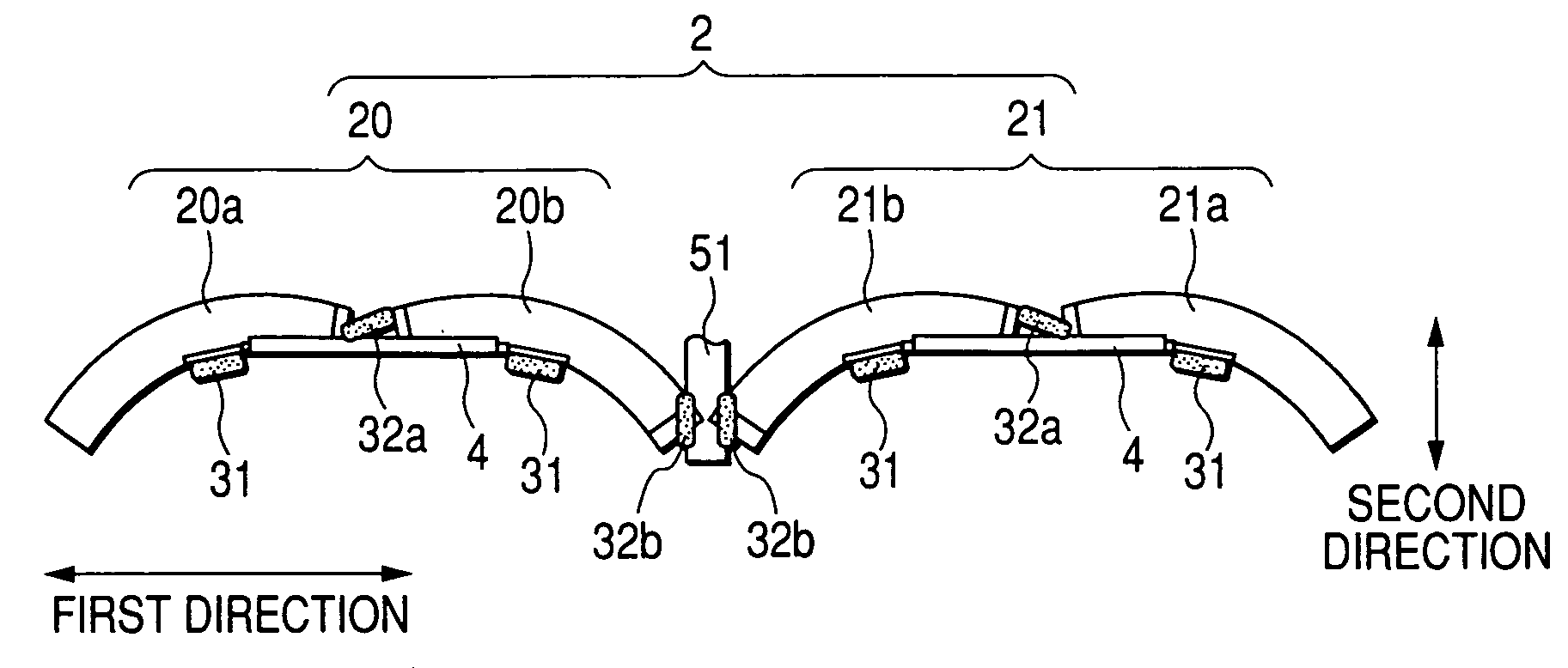
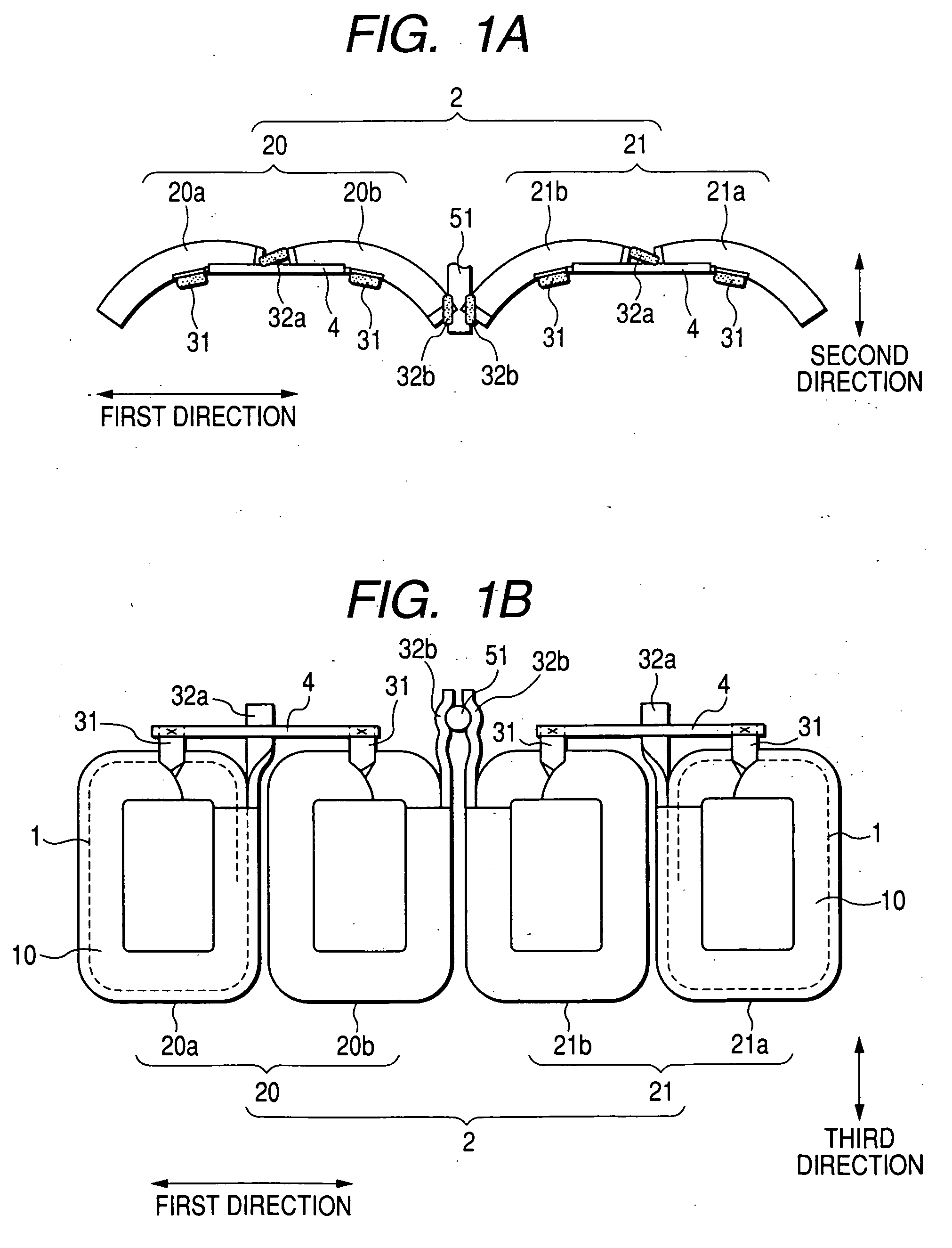
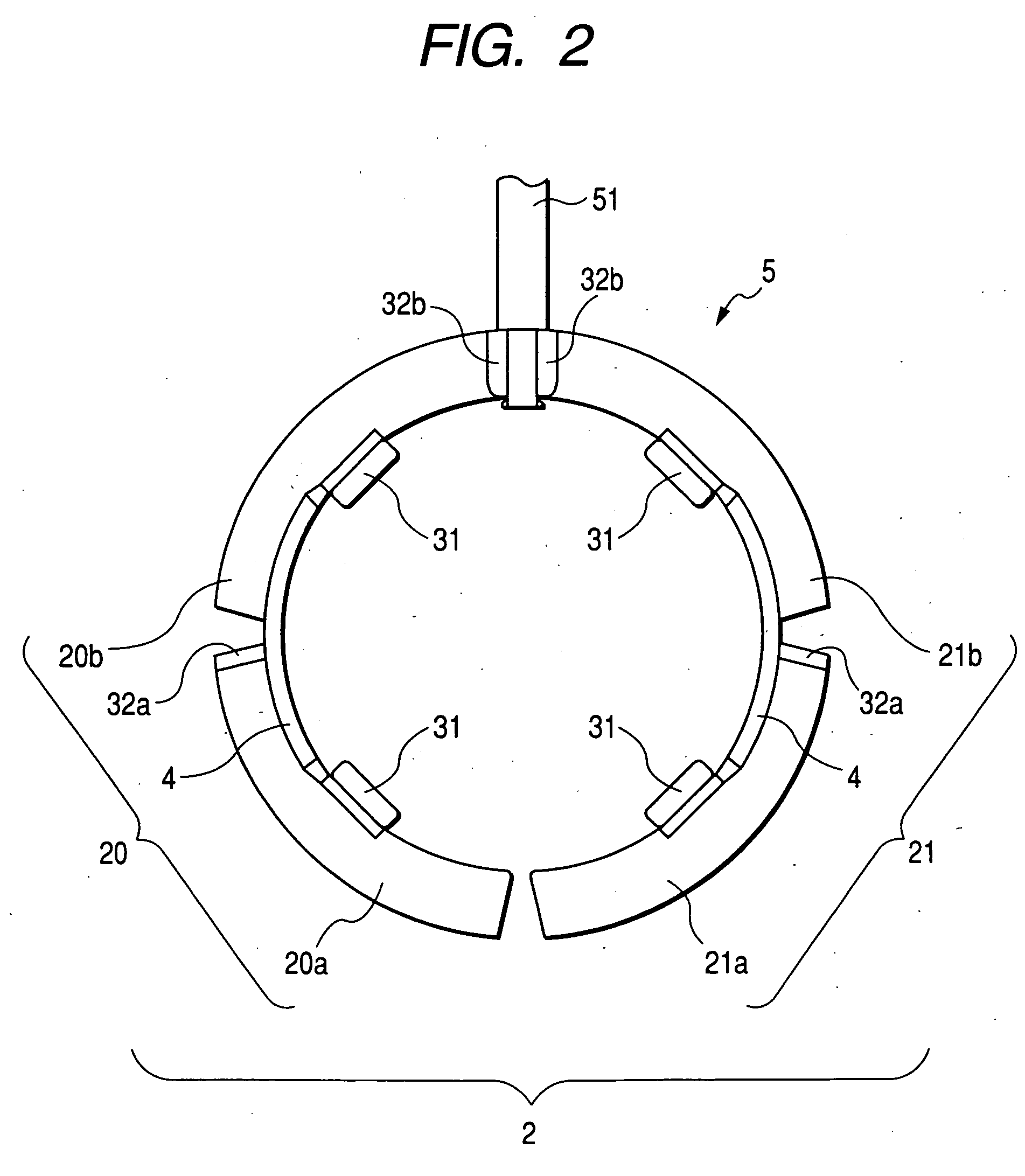
[0022]FIG. 1A is an upper plan view of a developed field coil according to a first embodiment, and FIG. 1B is a front view of the developed field coil. FIG. 2 is an upper plan view of the field coil formed in a cylindrical shape. FIG. 3 is an upper plan view of a field apparatus having the cylindrical field coil inserted into a yoke.

[0023] As shown in FIGS. 1A and 1B, a field coil 2 developed in a substantially flat-plate shape is initially manufactured. As shown in FIG. 2, the developed field coil 2 is made round into a cylindrical shape while bending connecting conductors 4 to obtain a cylindrical field coil 5. As shown in FIG. 3, the field coil 5 is inserted into a yoke 61 to assemble a field apparatus 6.

[0024] As shown in FIGS. 1A and 1B, the field coil 2 has two coupled coils 20 and 21. The coupled coil 20 has two coil units 20a and 20b. The coupled coil 21 has two coil units 21a and 21b. The coil units 20a, 20b, 21b and 21a are disposed in parallel to each other along a firs...

Example

[0039]FIG. 5 is a front view of a coupled coil according to a second embodiment. A coupled coil 22 according to a second embodiment differs from the coupled coil 20 or 21 in that a coil start terminal 31 of a coil unit 22a having a coil conductor 1 wound counterclockwise is drawn from the coil unit 22a and is directly connected with the terminal 31 of the coil unit 20b disposed adjacent to the coil unit 22a without using any connecting conductor 4. Therefore, the terminal 31 of the coil unit 22a acts as a crossover line. More specifically, the terminal 31 protruded from the coil unit 22a by a predetermined length is twisted, bent and extended in the same manner as in the first embodiment. Then, the terminal 31 is twisted and bent by almost 90 degrees so as to have a wider surface almost parallel to a coil surface 10 of the unit and to be extended toward the terminal 31 of the coil unit 20b. Thereafter, the terminal 31 of the coil unit 22a is attached to the surface of the terminal 3...


PUM


Abstract

A field apparatus has a tubular yoke and a field coil formed in a tubular shape and disposed on and fixed to an inner surface of the yoke. The field coil has a plurality of coil units disposed in parallel to each other along a circumferential direction of the yoke. The field coil further has a connecting conductor connecting free terminals of coil conductors of each pair of coil units to form a current path in the field coil. Each connecting conductor is curved along the circumferential direction of the yoke by bending the connecting conductor, and stiffness of the connecting conductor is lower than that of the coil conductor.

Description

CROSS-REFERENCE TO RELATED APPLICATION [0001] This application is based upon and claims the benefit of priority of the prior Japanese Patent Application 2005-102122 field on Mar. 31, 2005 so that the contents of which are incorporated herein by reference. BACKGROUND OF THE INVENTION [0002] 1. Field of the Invention [0003] The present invention generally relates to a field apparatus used for a rotary electric machine such as a starter of a vehicle, and more particularly to a field apparatus wherein each pair of coils in a field coil are connected with each other through a connecting conductor. The present invention further relates to a field coil used for the field apparatus. [0004] 2. Description of Related Art [0005] A conventional field apparatus for a starter of a vehicle is, for example, disclosed in Published Japanese Patent Second Publication No. H05-17778. This apparatus has a cylindrical yoke, a plurality of coils disposed on an inside surface of the yoke, a ring-shaped cros...

Claims


Application Information

Patent Timeline
IPC IPC(8): H02K3/00H02K23/02H02K3/04H02K1/12
CPCH02K3/522H02K3/18
Inventor UTSUNOMIYA, YAMATO
Owner DENSO CORP
Why Eureka
Try Eureka