

Optical pickup device
- Summary
- Abstract
- Description
- Claims
- Application Information
AI Technical Summary
Benefits of technology
Problems solved by technology
Method used
Image

Examples
embodiment 1
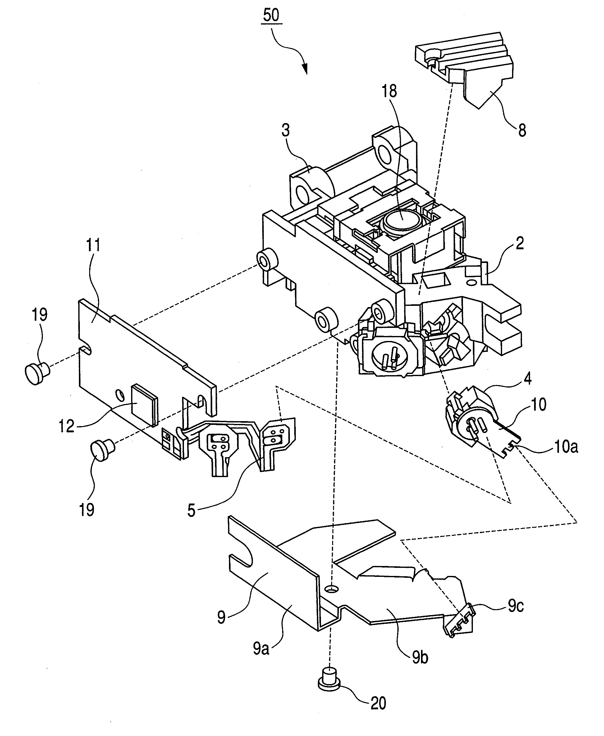
[0039]An optical pickup device which is the first embodiment of the present invention will be explained below referring to FIG. 1 to FIG. 4.
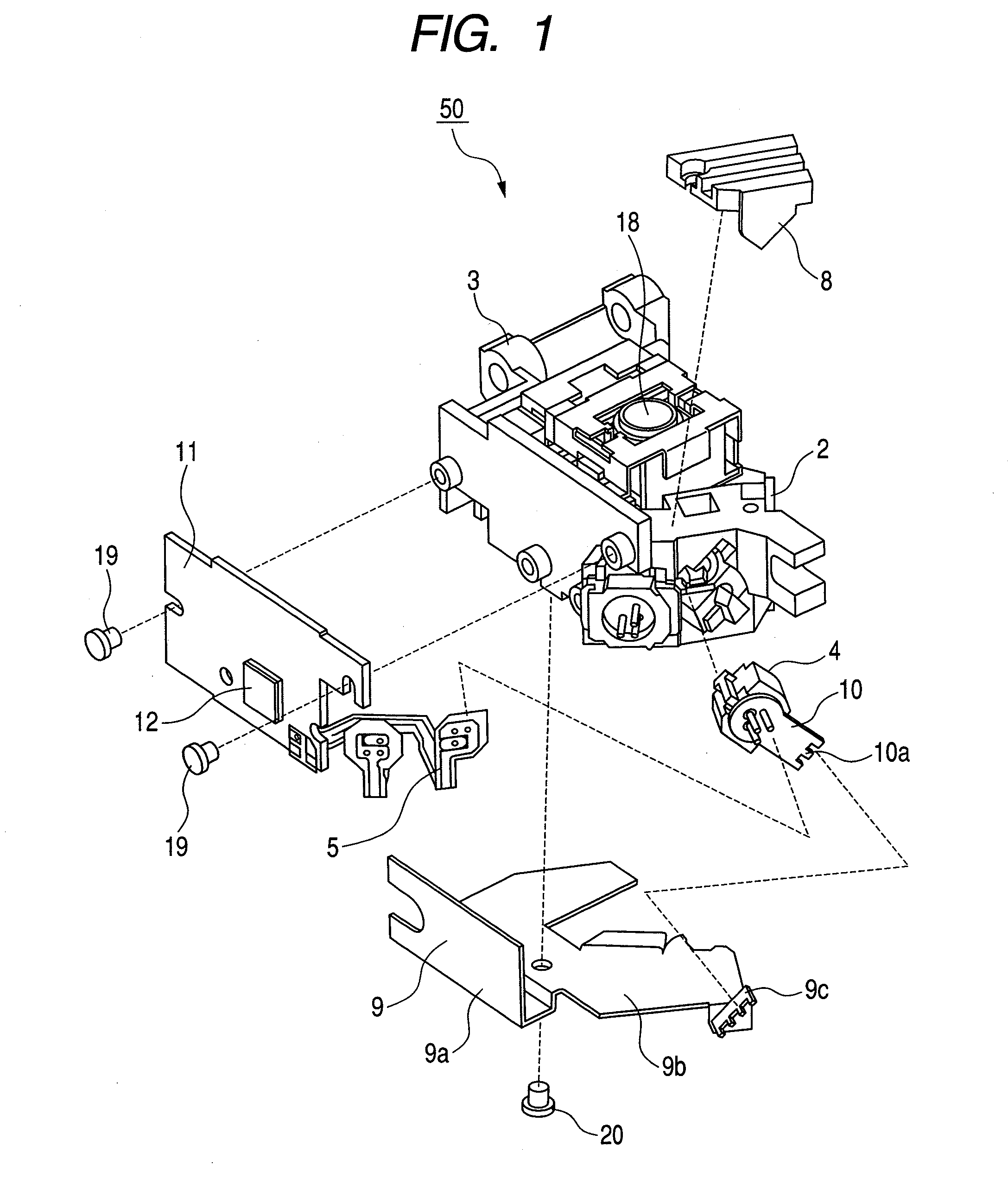
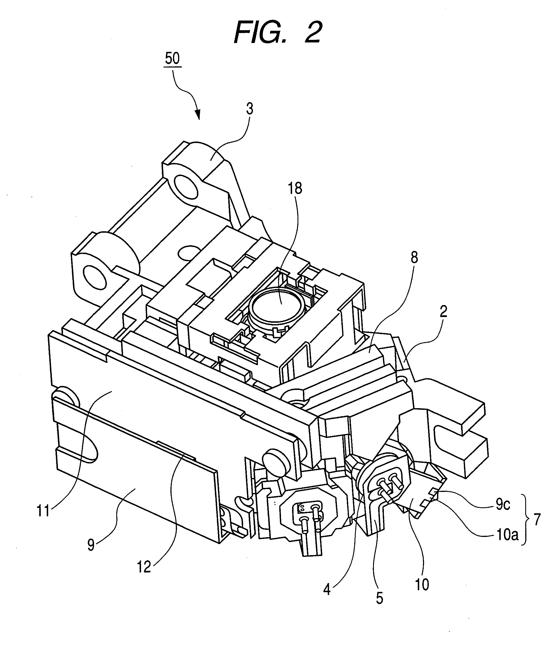
[0040]First, the whole configuration of optical pickup device 50 of the present embodiment is described with reference to FIG. 1 to FIG. 4. FIG. 1 is an exploded oblique perspective view of an optical pickup device of the present embodiment. FIG. 2 is an oblique perspective view of the assembled optical pickup device of the present embodiment shown in FIG. 1. FIG. 3 is an exploded oblique perspective view of a laser diode used in the present embodiment. FIG. 4 is an exploded oblique perspective view of the laser diode and its vicinity of the optical pickup device of the present embodiment. FIG. 5 is an oblique perspective view of the assembled optical pickup device of the present embodiment shown in FIG. 4.
[0041]Referring to FIG. 1 and FIG. 2, optical pickup device 50 is mainly equipped with a laser diode 1 (see FIG. 3), an optical system, a hou...
embodiment 2
[0067]An optical pickup device which is the second embodiment of the present invention will be explained below referring to FIG. 6. FIG. 6 is an explanatory drawing of a structure which connects a metallic member and a cover of an optical pickup device which is the second embodiment of the present invention. The second embodiment is basically the same as the first embodiment except for the following:
[0068]The structure of the present embodiment which connects the metallic member 10 and the cover 9 is designed to absorb the displacement due to adjustment and reduce the heat resistance. Substantially, the structure connects the metallic member 10 and the cover 9 with a graphite sheet 17. The graphite sheet 17 is flexible and high thermal-conductive and excellent as a material, which can transfer heat while absorbing the displacement of the laser diode 1 due to adjustment. A strand of fine copper wires can substitute for the graphite sheet 17. The graphite sheet 17 is fixed to the meta...
embodiment 3
[0069]An optical pickup device which is the third embodiment of the present invention will be explained below referring to FIG. 7. FIG. 7 is an explanatory drawing of a structure which connects a metallic member and a cover of an optical pickup device which is the third embodiment of the present invention. The third embodiment is basically the same as the first embodiment except for the following:
[0070]The third embodiment provides a curved surface whose center is aligned to the center of rotational adjustment between the metallic member 10 and the cover 9. This structure does not require a space to absorb the displacement of the laser diode 1 due to adjustment when the rotational adjustment of one axis of the laser diode 1 is done using the support member 4 which has the protrusion 6. However, also in this case, it is impossible to make the surface of the metallic member 10 and the surface of the cover 9 in contact with each other completely. So it is recommended to fill the space ...
PUM
 Abstract
Description
Claims
Application Information