Tactile sensation presenting device
- Summary
- Abstract
- Description
- Claims
- Application Information
AI Technical Summary
Benefits of technology
Problems solved by technology
Method used
Image
Examples
first embodiment
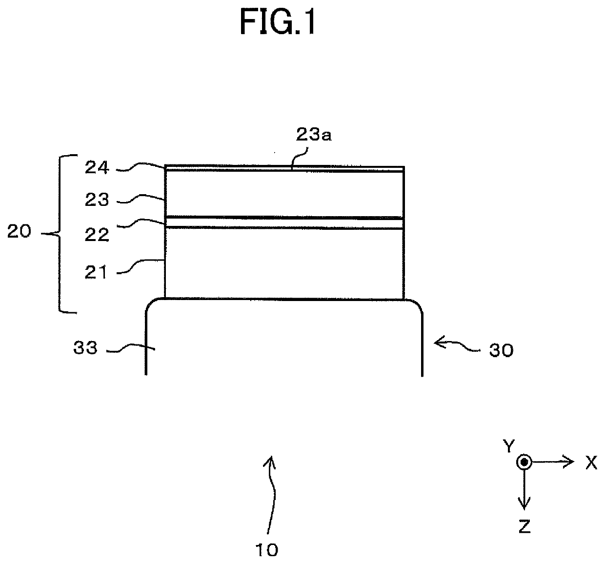
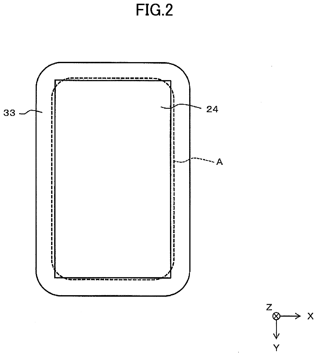
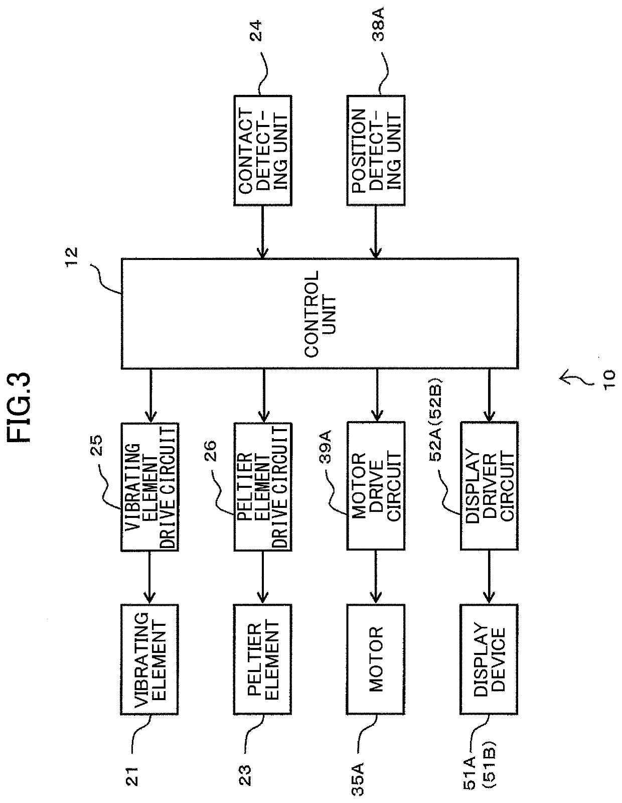
[0037]FIG. 1 is a side view illustrating a schematic configuration of a tactile sensation presenting device 10 according to a first embodiment; FIG. 2 is a plan view of the tactile sensation presenting device 10 that is illustrated in FIG. 1; and FIG. 3 is a functional block diagram of the tactile sensation presenting device 10. In each drawing, X-Y-Z coordinates are illustrated as reference coordinates. In the following description, a state viewed from the upper side to the lower side in the Z direction may be referred to as plan view, and the Z direction is a direction perpendicular to an X-Y plane.
[0038]As illustrated in FIG. 1 and FIG. 2, the tactile sensation presenting device 10 includes a pressure sensation generating unit 30 (pressure sensation generating unit 30A, 30B, 30C in FIG. 6A) and a tactile sensation generating unit 20 is arranged on a support 33 (33A, 33B, 33C in FIG. 6A) of the pressure sensation generating unit 30.
[0039]As illustrated in FIG. 1, a vibrating eleme...
second embodiment
[0098]FIG. 10 is a side view illustrating a schematic configuration of a tactile sensation presenting device 110 according to a second embodiment, and FIG. 11 is a plan view illustrating a schematic configuration of the tactile sensation presenting device 110 according to the second embodiment.
[0099]The tactile sensation presenting device 110 of the second embodiment differs from that of the first embodiment in that a pressure sensation generating unit 130 capable of tilting the tactile sensation generating unit 20 is used instead of the pressure sensation generating unit 30A, 30B, or 30C of the first embodiment. Because the contact area A and the configuration of the tactile sensation generating unit 20 are similar to those in the first embodiment, the same reference numerals are used.
[0100]As illustrated in FIG. 10 or FIG. 11, the pressure sensation generating unit 130 includes a fixed member 131, five pin-shaped air cylinders 132A, 132B, 132C, 132D, and 132E disposed on the fixed...
PUM
 Abstract
Description
Claims
Application Information
 - R&D
- Intellectual Property
- Life Sciences
- Materials
- Tech Scout
- Unparalleled Data Quality
- Higher Quality Content
- 60% Fewer Hallucinations
Browse by: Latest US Patents, China's latest patents, Technical Efficacy Thesaurus, Application Domain, Technology Topic, Popular Technical Reports.
© 2025 PatSnap. All rights reserved.Legal|Privacy policy|Modern Slavery Act Transparency Statement|Sitemap|About US| Contact US: help@patsnap.com


