Cage Assembly and Electrically Powered Tool Having Cage

a technology of cages and electric power tools, which is applied in the field of cages and electrical power tools, can solve the problems of compact design problems of electric power tools, and achieve the effects of compactness, compactness and miniaturization

Inactive Publication Date: 2019-11-14
BOSCH POWER TOOLS CHINA +1
View PDF0 Cites 2 Cited by
  • Summary
  • Abstract
  • Description
  • Claims
  • Application Information

AI Technical Summary

Benefits of technology

[0018]According to the present application, the design that the driving component and the execution component are jointly assembled to the holder to form the holder assembly before the embedding reduces the structural redundancy caused by the fixing and mating functions, thereby making the entirety more compact and miniaturized.

Problems solved by technology

The main problem to be solved by the present application is the compact design problem of the electric power tool.

Method used


Image

  • Cage Assembly and Electrically Powered Tool Having Cage
  • Cage Assembly and Electrically Powered Tool Having Cage
  • Cage Assembly and Electrically Powered Tool Having Cage

Examples


Embodiment Construction

[0039]Specific embodiments of the present application are described in detail below in conjunction with the accompanying drawings. In various drawings, the same or similar components are denoted by the same reference numerals. At the same time, it should be understood that the drawings are merely used to illustrate the present application, and the dimensions of the components, the scale and the number of the components in the drawings are not intended to limit the present application. Furthermore, it should be noted in advance that the so-called terms “front” and “front end” in the present application refer to the end of the electric power tool that is axially close to an object to be operated, and “rear” and “rear end” refer to the end of the electric power tool that is axially far away from the object to be processed.

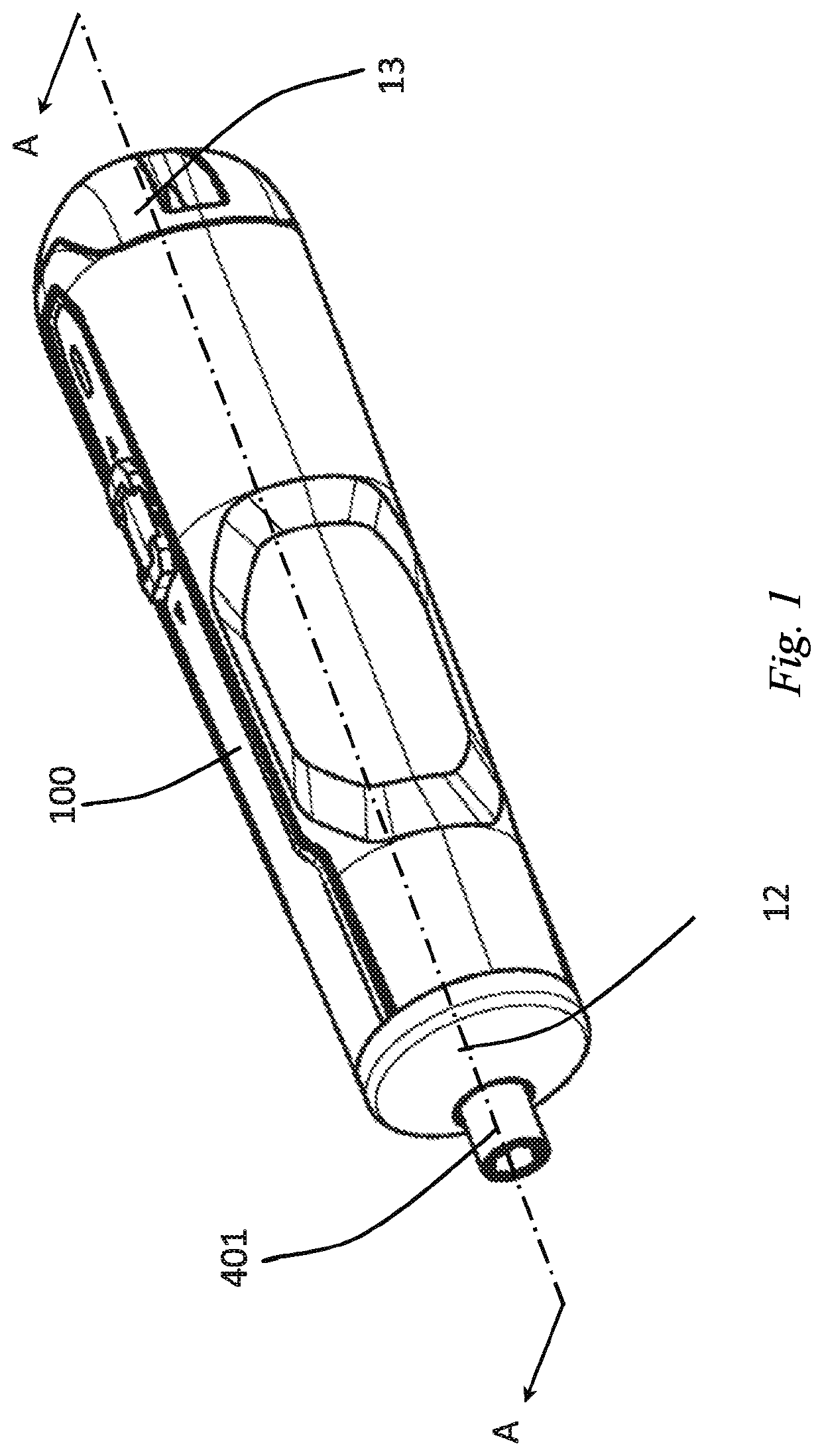
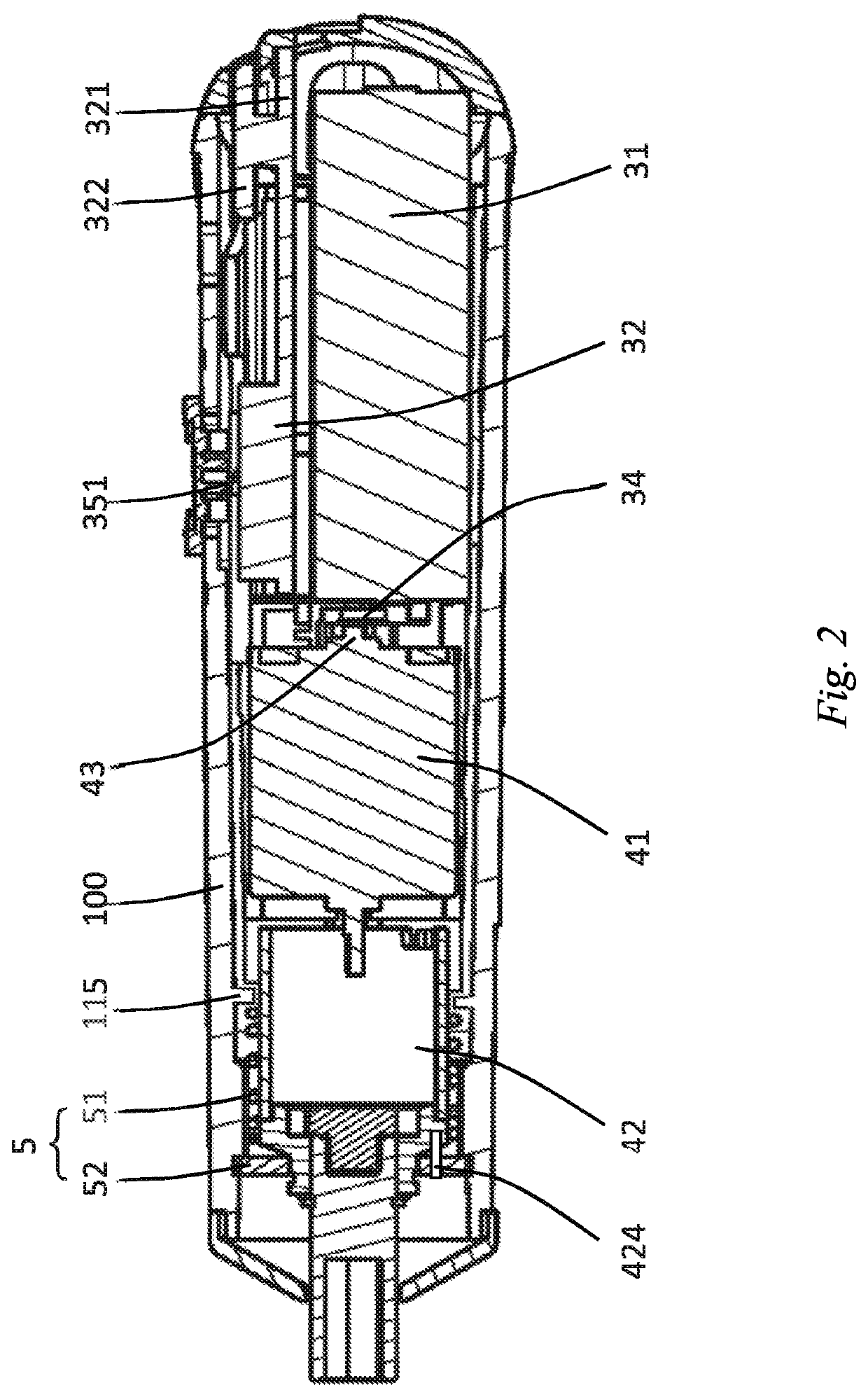
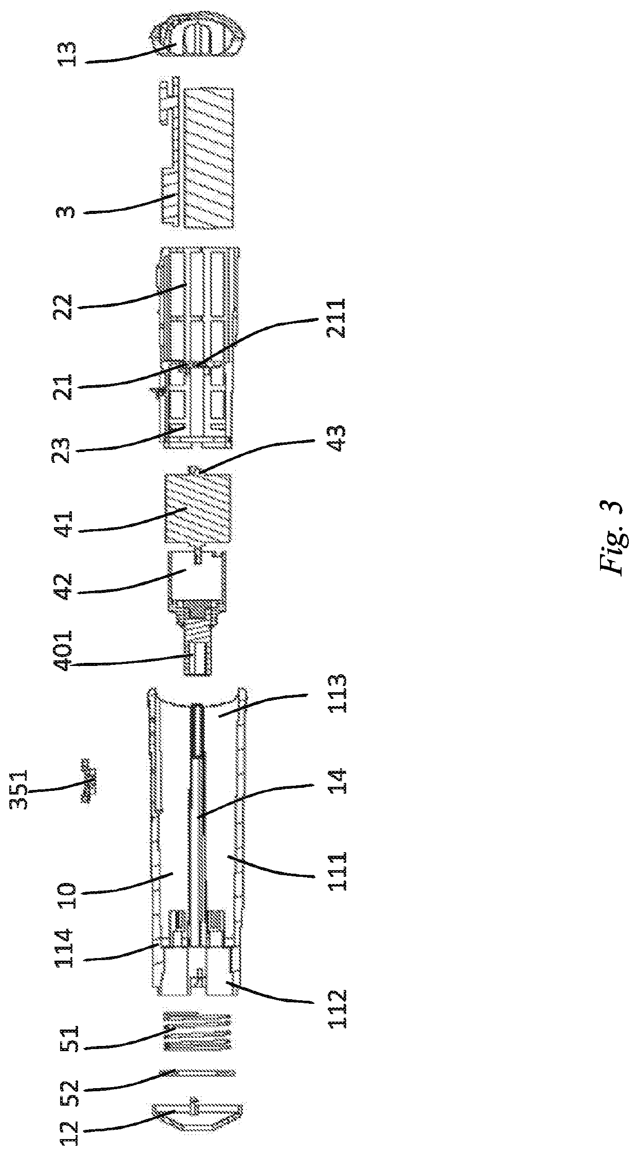
[0040]Referring to FIGS. 1 to 6, and particularly referring to FIGS. 3 and 4, an electric power tool provided in a specific embodiment of the present application is a...


PUM


Abstract

An electrically powered tool includes a cage assembly that has a cage, driving component, executing component, and cylindrical housing. The cage includes a base, a rear cage extending rearwards from the base, and a front cage extending forwards from the base. The driving component is positioned on the rear cage. The executing component is positioned on the front cage, and includes an output shaft extending forwards. The driving and executing components are positioned on the cage so as to form the cage assembly. The cage assembly is received in the cylindrical housing, and is configured to be mounted in the cylindrical housing in a modular fashion. Prior to insertion in the housing, the driving and executing components are jointly mounted into the cage to form the cage assembly so as to reduce structural redundancy via fixing and fitting, such that an overall body of the assembly smaller and more compact.

Description

TECHNICAL FIELD[0001]The present application relates to an electric power tool, and in particular to an electric power tool having a holder.BACKGROUND ART[0002]Electric power tools, such as electric screwdrivers, typically comprise batteries, circuit boards, electric motors, gearboxes, and other related components. In recent years, ever-increasing functions, such as torque control and power management, have brought more complex and larger-sized circuit board designs. In addition, the structural limitations of the axial superposition of many components pose a challenge for the miniaturized design of the electric power tools. At the same time, due to the large number of scattered parts, the general electric power tool often has a two-piece housing that is split in half, and the assembly is completed by bolting the housing and clamping the parts. However, such a design requires bolt holes pre-formed in the housing, which is another reason for restricting the compactness and miniaturiza...

Claims


Application Information

Patent Timeline
Patent Type & Authority Applications(United States)
IPC IPC(8): B25F5/02
CPCB25F5/021B25F5/029B25F5/00B25F5/02
Inventor CHEN, WEI
Owner BOSCH POWER TOOLS CHINA
Why Eureka
Try Eureka