Ventilated and draining foam insulation panel for building construction

a technology of foam insulation panel and ventilation and draining foam, which is applied in the direction of heat insulation, walls, building components, etc., can solve the problems of inadequate insulation, adverse consequences, mold and/or rot,

Inactive Publication Date: 2019-11-14
ADVANCED BUILDING PRODS
View PDF6 Cites 7 Cited by
  • Summary
  • Abstract
  • Description
  • Claims
  • Application Information

AI Technical Summary

Problems solved by technology

Failure to adequately remove moisture can lead to adverse consequences, for example, mold and / or rot.

Method used


Image

  • Ventilated and draining foam insulation panel for building construction
  • Ventilated and draining foam insulation panel for building construction
  • Ventilated and draining foam insulation panel for building construction

Examples


Embodiment Construction

[0015]Referring to the figures, the ventilated and draining foam insulation panel for a wall, floor, and / or roof is illustrated.

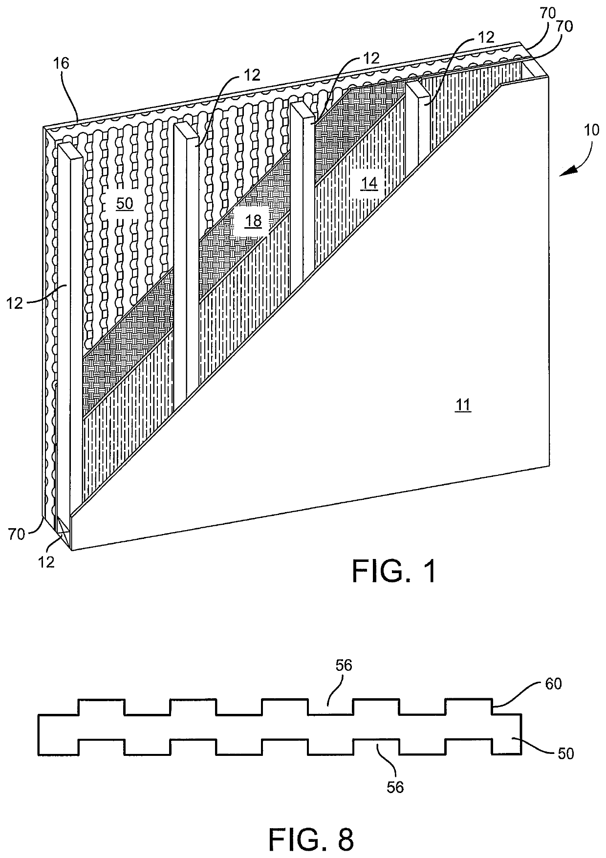
[0016]FIG. 1 shows a wall 10, parts broken away for clarity (the invention is not limited to wall, as discussed below). Wall 10 shows frame 12 (having studs and plates) with a conventional interior cladding 11 (e.g., drywall, paneling), a conventional sheathing 14 (e.g., OSB, foam board, plywood), an optional, but preferred, a conventional moisture barrier 18 (e.g., house wrap), foam insulation panel 50, a veneer (or exterior cladding) 16, an vents 70.

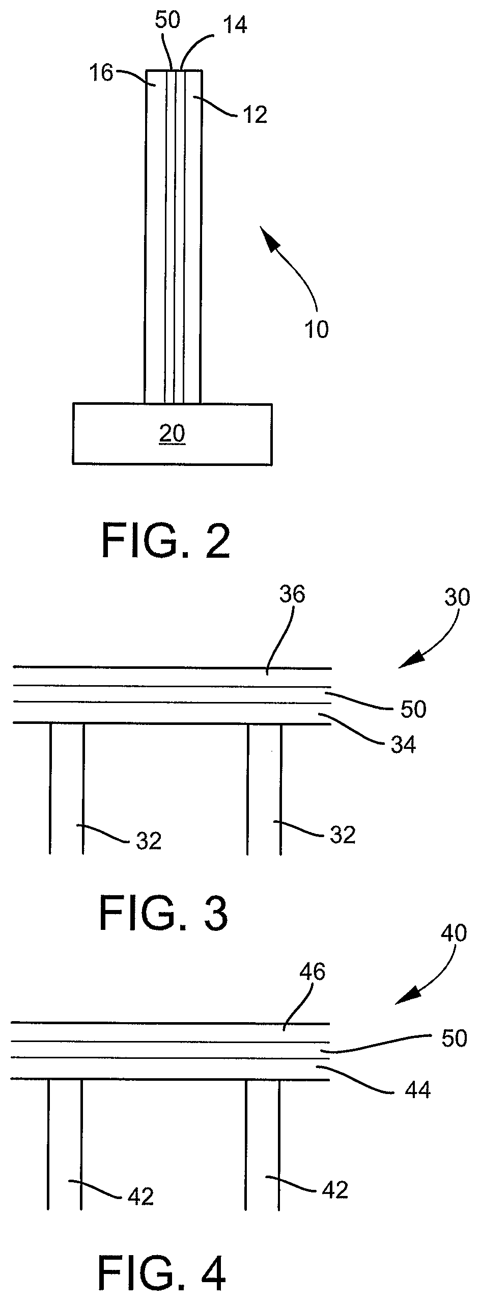
[0017]FIG. 2 is a schematic illustration of an embodiment of a cross-section of a wall system 10 on a foundation 20. The wall system 10 generally includes: a frame 12, a sheathing 14 affixed to the frame 12, a foam insulation panel 50 (discussed in greater detail below) affixed over the sheathing 14, and a veneer 16 (e.g., brick, stucco, siding). Optionally, the wall system 10 may include a vapor barrier (e.g....


PUM

PropertyMeasurementUnit
thicknessaaaaaaaaaa
depthaaaaaaaaaa
thicknessaaaaaaaaaa

Abstract

A method for facilitating ventilation and/or drainage in a building wall, floor, and/or roof by the step of: placing a foam insulation board with an interior board face and an exterior board face, at least one board face having ventilation and/or drainage grooves and/or protrusions into the building wall, floor, and/or roof; providing vents in the building wall, floor, and/or roof adjacent end portions of the insulation board, whereby ventilation is facilitated within the wall, floor, and/or roof of the building by air moving through the vents, along the grooves and/or protrusions of the foam insulation board, and out of the vents, drainage of water is facilitated within the wall or the roof of the building by a pathway created by the grooves and/or protrusions, and moisture removal is facilitated by the passage of air during ventilation.

Description

RELATED APPLICATIONS[0001]This application claims the benefit of U.S. Provisional Patent Application Ser. No. 62 / 670,019 filed May 11, 2018; U.S. Provisional Patent Application Ser. No. 62 / 732,742 filed Sep. 18, 2018; and U.S. Provisional Patent Application Ser. No. 62 / 743,594 filed Oct. 10, 2018, each of which is incorporated herein by reference.FIELD OF THE INVENTION[0002]The invention is directed to removal of moisture from the wall, floor, and / or roof of a building.BACKGROUND OF THE INVENTION[0003]In building construction (residential and / or commercial), moisture removal from within a wall, floor, and / or roof is an important consideration. Failure to adequately remove moisture can lead to adverse consequences, for example, mold and / or rot. Some contemporary solutions are to promote airflow, ventilation, and drainage within the wall floor, and / or roof by, for example, the use of an entangled net product. The air movement is used to move any moisture out of the wall, floor, and / or...

Claims


Application Information

Patent Timeline
Patent Type & Authority Applications(United States)
IPC IPC(8): E04B1/70E04B1/80
CPCE04B2001/7691E04B1/80E04B1/7069E04B2/707E04C2/205E04C2/322E04C2/326E04C2/523
Inventor LOLLEY, KEITH A.
Owner ADVANCED BUILDING PRODS
Why Eureka
Try Eureka