System and method for mechanical fastening designs

a technology of mechanical fastening and design, applied in the field of system and method of mechanical fastening design, can solve the problems of distortion of the visualized structure, difficulty in visualizing the internal structure, and inability to achieve accurate and detailed results

Inactive Publication Date: 2019-11-28
MEDIPRINT LLC
View PDF0 Cites 2 Cited by
  • Summary
  • Abstract
  • Description
  • Claims
  • Application Information

AI Technical Summary

Benefits of technology

[0013]Accordingly, apparatus and methods to present sectioned physical models in a manner that allows for straightforward disassembly and reassembly to allow for inspection of internal structure on cross sectioned pieces are presented. By creating a tangible model which is segmented, layered, or otherwise able to be disassembled and reassembled again, one is able to present views of the interior or otherwise obscured portions of an object. In some examples, the segmented model corresponds to a patient-specific body part. The replacement body part is created from a model that is produced in vivo, non-invasively, and with sufficient accuracy and detail to be used to guide later surgery.
[0015]Embodiments in accordance with the present disclosure provide for a system and method to create a patient-specific replacement body part which may then be displayed in manners that allow for easy disassembly and reassembly. Imaging scans are acquired by modalities such as magnetic resonance imaging (MRI) or computed tomography (CT), and are stored as image data in standard DICOM format in order to promote data portability and interoperability. The data may be further processed to a format compatible with a fabrication apparatus such as a 3-D printer or other automated maker to directly create medical models or medical replacement parts from the imaging scans.

Problems solved by technology

In various examples, the internal structure of the physically rendered model may become impossible or difficult to visualize due to being imbedded behind externally displayed features.
Even so, the visualization of the internal structure may be difficult, and distortions of the visualized structure occur.
Cross-sectioned pieces may have complicated shapes, and although it is typically straightforward to separate pieces that have been cut in cross section, it may be very difficult to reorient these pieces in their correct configuration.
Compared with CT scans, MRI scans typically take longer and are louder, and they usually need the patient to enter a narrow, confining tube.
In addition, patients with some medical implants or other non-removable metal inside the body may be unable to undergo an MRI examination safely.

Method used


Image

  • System and method for mechanical fastening designs
  • System and method for mechanical fastening designs
  • System and method for mechanical fastening designs

Examples


Embodiment Construction

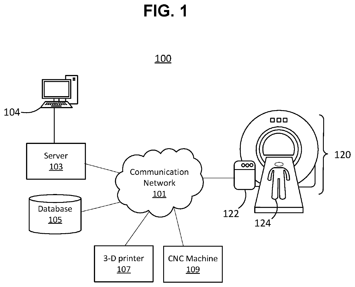
[0026]FIG. 1 illustrates a system 100 to design a patient-specific medical model. System 100 includes an MRI machine 120, illustrated as accommodating a patient 124 laying on a gurney and about to undergo MRI examination. MRI machine 120 may include a local control console 122, by which the local operation of MRI machine 120 may be controlled. For example, at local control console 122, an MRI operator (not shown) may control local operation such as movement of the patient gurney to move patient 124 into and out of MRI machine 120, starting and stopping other functions or operating modes of MRI machine 120, etc. Although FIG. 1 illustrates MRI machine 120 as the modality, other modalities such as a CT machine are contemplated as being compatible with system 100.

[0027]MRI machine 120 communicatively interfaces with a communication network 101. Communication network 101 may include, e.g., at least a portion of an Ethernet network, the design of which is well known to persons of skill i...


PUM


Abstract

The present disclosure describes systems and methods to create three-dimensional tangible models which may be taken apart and reassembled with ease and accuracy. The three-dimensional tangible models may be segmented, layered, or otherwise able to be disassembled and reassembled again, so one is able to present views of an interior or otherwise obscured portion of a tangible object. In some examples, a tangible segmented model corresponds to a patient-specific body part.

Description

CROSS REFERENCES TO RELATED APPLICATIONS[0001]This application claims priority to U.S. Provisional Patent Application Ser. No. 62 / 699,827, entitled “SYSTEM AND METHOD FOR MECHANICAL FASTENING DESIGN”, filed on Jul. 18, 2018 and as a continuation to U.S. Non-Provisional patent application Ser. No. 16 / 372,947 tilted “APPARATUS AND METHODS FOR CREATION OF A PATIENT-SPECIFIC ANATOMICAL MODEL”, filed on Apr. 2, 2019 and as a continuation to U.S. Non-Provisional patent application Ser. No. 16 / 373,114 entitled “APPARATUS AND METHODS FOR CREATION OF A PATIENT-SPECIFIC BODY PART OR MEDICAL INSERT”, filed on Apr. 2, 2019 each of which are relied upon and incorporated herein by this reference.FIELD OF THE DISCLOSURE[0002]The present disclosure relates to systems and methods to create tangible three-dimensional models which may be taken apart and reassembled with ease and accuracy.BACKGROUND OF THE DISCLOSURE[0003]Complex three-dimensional models have many applications in medicine, teaching, an...

Claims


Application Information

Patent Timeline
Patent Type & Authority Applications(United States)
IPC IPC(8): G05B19/4099G16H30/20G06F3/12B33Y50/00
CPCG06F3/1232B33Y50/00G16H30/20G05B2219/35134G05B2219/49007G06F3/1206G06F3/1297G05B19/4099G06F3/1286B33Y80/00G16H40/67G16H50/20G16H50/50G06F3/1285G06F3/1244
Inventor CHANIN, BRENT
Owner MEDIPRINT LLC
Why Eureka
Try Eureka