
Polychrometer and method for correcting stray lights of the same

Active Publication Date: 2009-03-05
KONICA MINOLTA SENSING INC
View PDF3 Cites 7 Cited by
  • Summary
  • Abstract
  • Description
  • Claims
  • Application Information

AI Technical Summary

Benefits of technology

[0007]In view of the above situation, an object of the present invention is to provide a polychrometer capable of correcting stray light with sufficient accuracy based on easily obtainable information and a method for correcting stray light of the polychrometer.
[0008]In a polychrometer and a method for correcting stray light of the polychrometer, relative spectral (inter-pixel) distribution of stray light independent of a spectral distribution of an incident light is obtained, intensity coefficient of the stray light is calculated according to spectral (inter-pixel) distribution of the incident light, and spectral (inter-pixel) distribution of the stray light included in a spectral (inter-pixel) distribution of an incident light is estimated and corrected. Thus, according to the polychrometer and the method for correcting stray light of the polychrometer according to the present invention, the stray light can be more accurately corrected as compared with a conventional case where stray light distribution is directly estimated from an incident light.

Problems solved by technology

It takes time and cost to obtain necessary accuracy.

Method used


Image

  • Polychrometer and method for correcting stray lights of the same
  • Polychrometer and method for correcting stray lights of the same
  • Polychrometer and method for correcting stray lights of the same

Examples


first embodiment

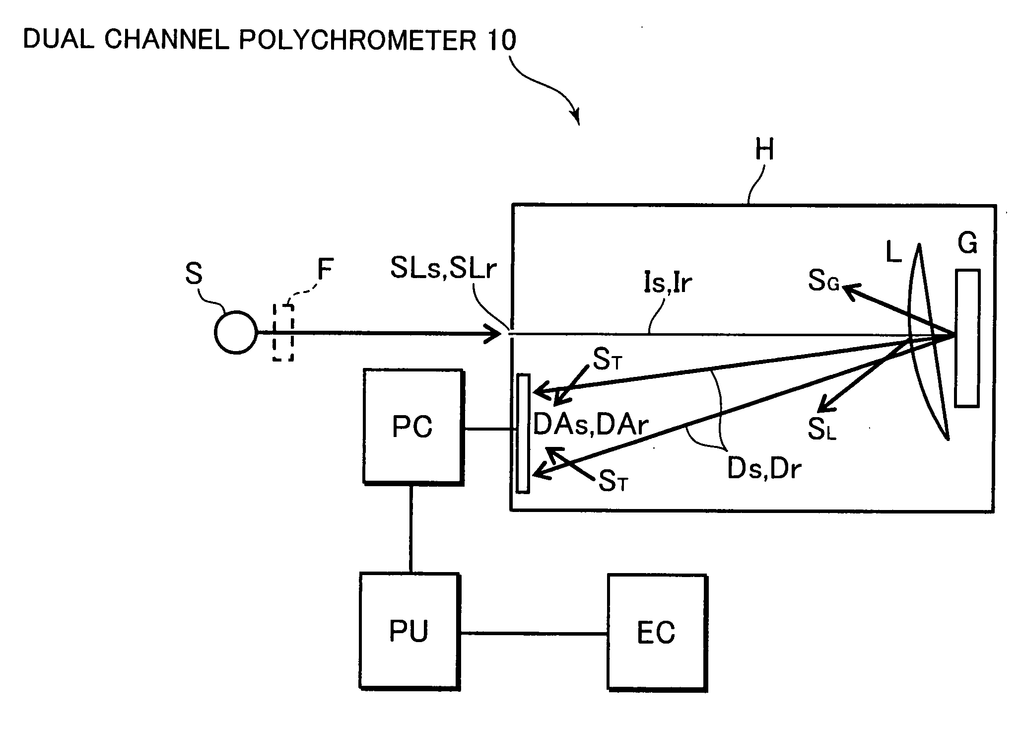
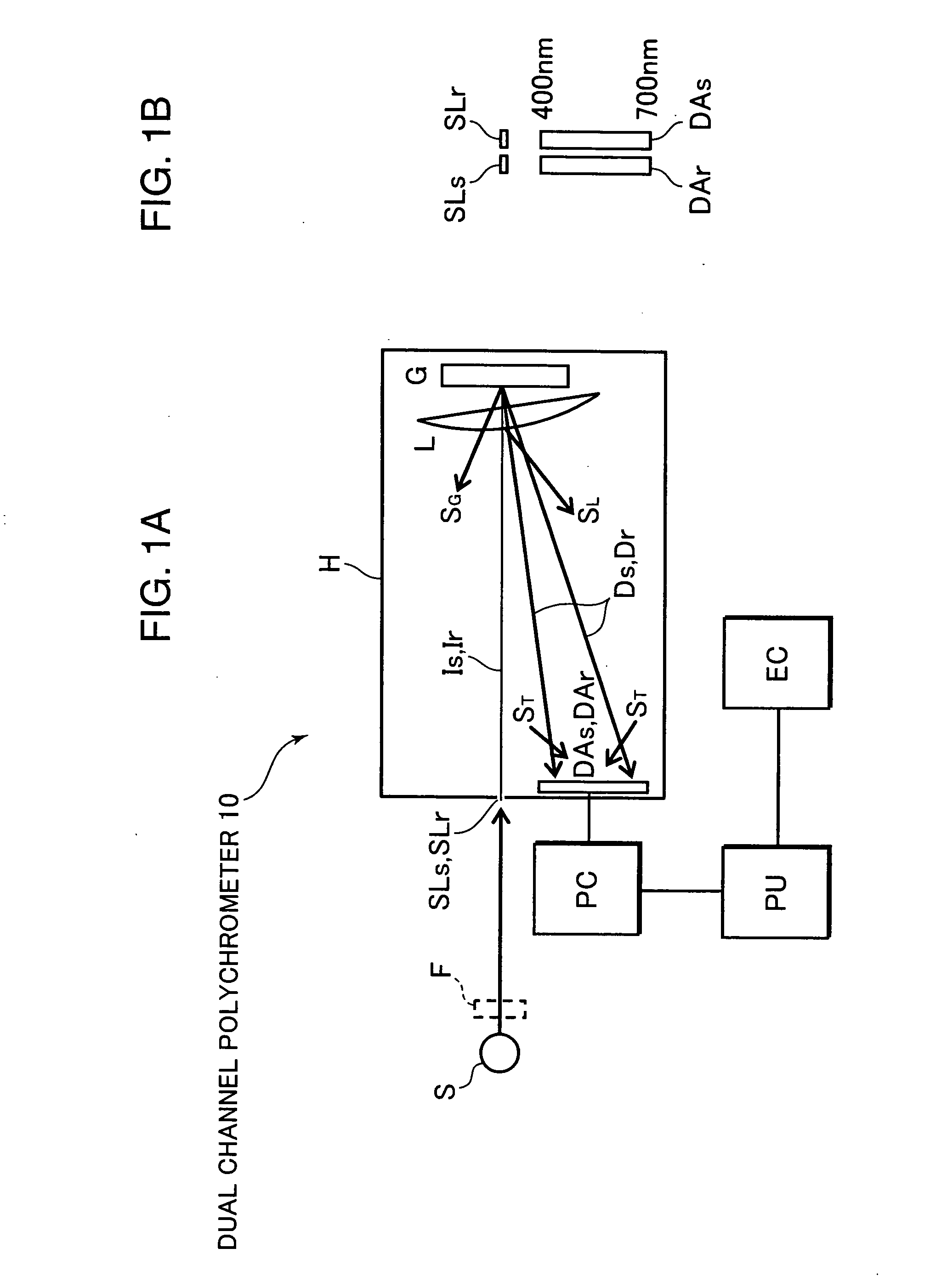
[0022]FIG. 1 is a block diagram of a dual channel polychrometer 10 as a polychrometer according to one embodiment. In this dual channel polychrometer 10, beams I (Is, Il) incident on incident slits SL (SLs, SLr) from a light source S are roughly converted into parallel beams by a lens L to be incident on a diffraction grating G, thereby being diffused and reflected, and diffused images of the incident slits SL (SLs, SLr) are formed and gathered on sensor arrays DA (DAs, DAr) by the lens L. Each sensor array DA (DAs, DAr) includes, for example, 35 pixels having pixel numbers n=1 to 35 and covers a wavelength range of 380 to 720 nm.

[0023]This dual channel polychrometer 10 is used as a spectral portion of a spectrocolorimeter (spectral reflection characteristic measuring apparatus) for illuminating a sample and measuring a spectral reflection coefficient of the sample. Thus, this dual channel polychrometer 10 is provided with two optical systems: a sample channel (hereinafter, S-channe...


PUM


Abstract

In a polychrometer and a method for correcting stray light of the polychrometer, relative spectral (inter-pixel) distribution of stray light independent of a spectral distribution of an incident light is obtained, intensity coefficient of the stray light is calculated according to spectral (inter-pixel) distribution of the incident light, spectral (inter-pixel) distribution of the stray light included in a spectral (inter-pixel) distribution of an incident light is estimated and corrected. Thus, the stray light can be more accurately corrected as compared with a conventional case where stray light distribution is directly estimated from an incident light.

Description

[0001]This application is based on Japanese Patent Application No. 2007-220415 filed on Aug. 27, 2007, the contents of which are hereby incorporated by reference.BACKGROUND OF THE INVENTIONField of the Invention[0002]The present invention relates to a polychrometer for measuring a spectral intensity distribution of a measurement light to be measured and a spectral reflection characteristic of a measurement sample to be measured, and a method for correcting stray light.Description of the Background Art[0003]A polychrometer for simultaneously measuring spectral intensities at all wavelengths of a measurement wavelength range is widely used as spectral means of a spectrophotometer (spectral intensity measuring apparatus) for measuring a spectral intensity distribution of a measurement light and a spectrocolorimeter (spectral reflection characteristic measuring apparatus) for measuring a spectral reflection characteristic of a sample because of its features of having high measurement ef...

Claims


Application Information

Patent Timeline
IPC IPC(8): G01J3/28
CPCG01J3/02G01J3/28G01J3/0294
Inventor IMURA, KENJI
Owner KONICA MINOLTA SENSING INC
Learn More