Receiver circuit and method using selectively variable amplification for receiving time signals from different transmitters

a time signal and receiver circuit technology, applied in multiplex communication, instruments, horology, etc., can solve the problems of amplification, decoding and subsequent evaluation of time data, and the optimum signal level of the amplified signal output of the amplifier, so as to achieve sufficient accuracy, reliability and security, and ensure the effect of receiving sensitivity

Active Publication Date: 2008-02-19
ATMEL CORP +2
View PDF58 Cites 10 Cited by
  • Summary
  • Abstract
  • Description
  • Claims
  • Application Information

AI Technical Summary

Benefits of technology

[0018]In view of the above, it is an object of the present invention to develop a receiver circuit, a radio-controlled clock, and a method by which the receiver sensitivity can be made more independent of the transmission frequency. Particularly, the receiver sensitivity shall be substantially or nearly constant and uniform independently of the transmission frequency of the received time signal. In that regard, the reception sensitivity shall be sufficiently high so as to receive, decode, and evaluate any received time signal within the entire pertinent frequency range of possible transmission frequencies, with a sufficient accuracy, reliability and security, without leading to an excessive power consumption and thus energy consumption. The invention further aims to avoid or overcome the disadvantages of the prior art, and to achieve additional advantages, as apparent from the present specification. The attainment of these objects is, however, not a required limitation of the claimed invention.
[0023]In comparison to the prescribed fixed or constant amplification factor of an amplifier in a conventional receiver circuit of a radio-controlled clock, the inventive provision of a receiver circuit with a variable adjustable amplification allows the amplification to be optimally adjusted or tuned depending on the transmission frequency of the time signal being received. This takes into account the fact that the reception signal strength or level of the received signal typically depends on the transmission frequency of that signal, with lower frequency signals typically having a lower reception signal strength. Thus, the invention allows such signals with a lower reception signal strength to be amplified with a higher amplification factor in comparison to the amplification factor used for amplifying a higher frequency signal that typically has a higher reception signal strength.
[0024]According to the invention, the amplification factor can be adjusted or selected so that the receiver circuit and / or the subsequent connected decoding and evaluating arrangement achieves a nearly constant reception sensitivity independent of the transmission frequency of the respective time signal being received. This simplifies and improves the accuracy of the decoding and evaluating of the received time informations, especially for such time signals that have been transmitted with a relatively low transmission frequency and thus typically would be received by the radio-controlled clock with a relatively low reception signal strength. Since the amplification factor is optimally adjusted for the respective signal being received, dependent on the transmission frequency thereof, this also ensures that the power consumption and thus energy consumption needed for the respective amplification will also be optimized, i.e. minimized for the particular prevailing circumstances.
[0037]According to a further advantageous embodiment of the invention, a second amplifier is provided and connected after or downstream from the first amplifier. This second amplifier serves to post-amplify the time signal that has already been amplified in the first amplifier and bandpass filtered in the selection devices. The use of such a second amplifier following the first amplifier is especially advantageous for energetic reasons. Namely, in this manner, it is possible to distribute the total cross-current or shunt current that is required for the total amplification among the plural amplifier stages. Thus, the individual components of the amplifier stages can be dimensioned smaller, whereby these exhibit a smaller total power consumption and thus a smaller total energy consumption.
[0040]In a very advantageous further development of the invention, the adjustable amplifier comprises a base amplification that is especially designed or adapted to the requirements for an average frequency within a frequency range of the several transmission frequencies of the time signals of all possible or available time signal transmitters. Thereby, the receiver can easily be tuned to a particular transmission frequency deviating from the average frequency with only slight variations of the actual amplification factor from the base amplification.
[0041]The control arrangement is advantageously realized by a hard-wired logic circuit, for example an FPGA circuit or a PLD circuit. Fundamentally, the functionality of the control arrangement can also be carried out by a microcontroller that is typically already available in a radio-controlled clock circuit. Nonetheless, a special advantage of the solution according to the invention is that the adjustment of the amplification factor can be realized in a very simple manner through simple circuit technical means, namely in the control arrangements according to the invention, without having to burden the microcontroller in this regard. Thus, the resources of the microcontroller remain available for other tasks, for example for the decoding and evaluation of the time signal, the treatment of interferences in the time signal, and / or any other user-specific tasks.

Problems solved by technology

This requirement poses new problems for the reception, amplification, decoding, and evaluation of the respective time signals.
In this regard it is problematic, however, that the amplifier of the receiver circuit conventionally has a constant fixed amplification factor, so that it always amplifies the respective received time signal with the same amplification, regardless whether the received time signal has a relatively lower received signal strength or amplitude or a relatively higher signal strength or amplitude.
Thus, the amplified signal output by the amplifier does not always have the optimum signal level for its further processing.
This can lead to problems and errors in the decoding and the subsequent evaluation of the time data encoded in the time signal.
The problem arises, however, that other time signals having a higher transmission frequency and thus typically a higher received signal amplitude, will be amplified at the same high amplification factor, leading to over-amplification of such signals.
This has various disadvantages, in comparison to a circuit with a lower amplification factor that would be completely adequate for such received signals having a high received signal amplitude.
This directly leads to higher costs of the circuit for providing a higher power amplifier, and especially also causes a higher power consumption of the amplifier circuit, because the higher amplification factor requires higher amplifier currents and thus directly a higher power consumption.
Thus, in the above described systems, the amplifier designed for the “worst case scenario”, leads to a relatively short operating life of the batteries, or the need to frequently recharge the accumulators.

Method used


Image

  • Receiver circuit and method using selectively variable amplification for receiving time signals from different transmitters
  • Receiver circuit and method using selectively variable amplification for receiving time signals from different transmitters
  • Receiver circuit and method using selectively variable amplification for receiving time signals from different transmitters

Examples


Embodiment Construction

[0056]In all of the drawing figures, the same elements and signals, as well as the elements and signals respectively having the same functions, are identified by the same reference numbers, unless the contrary is indicated.

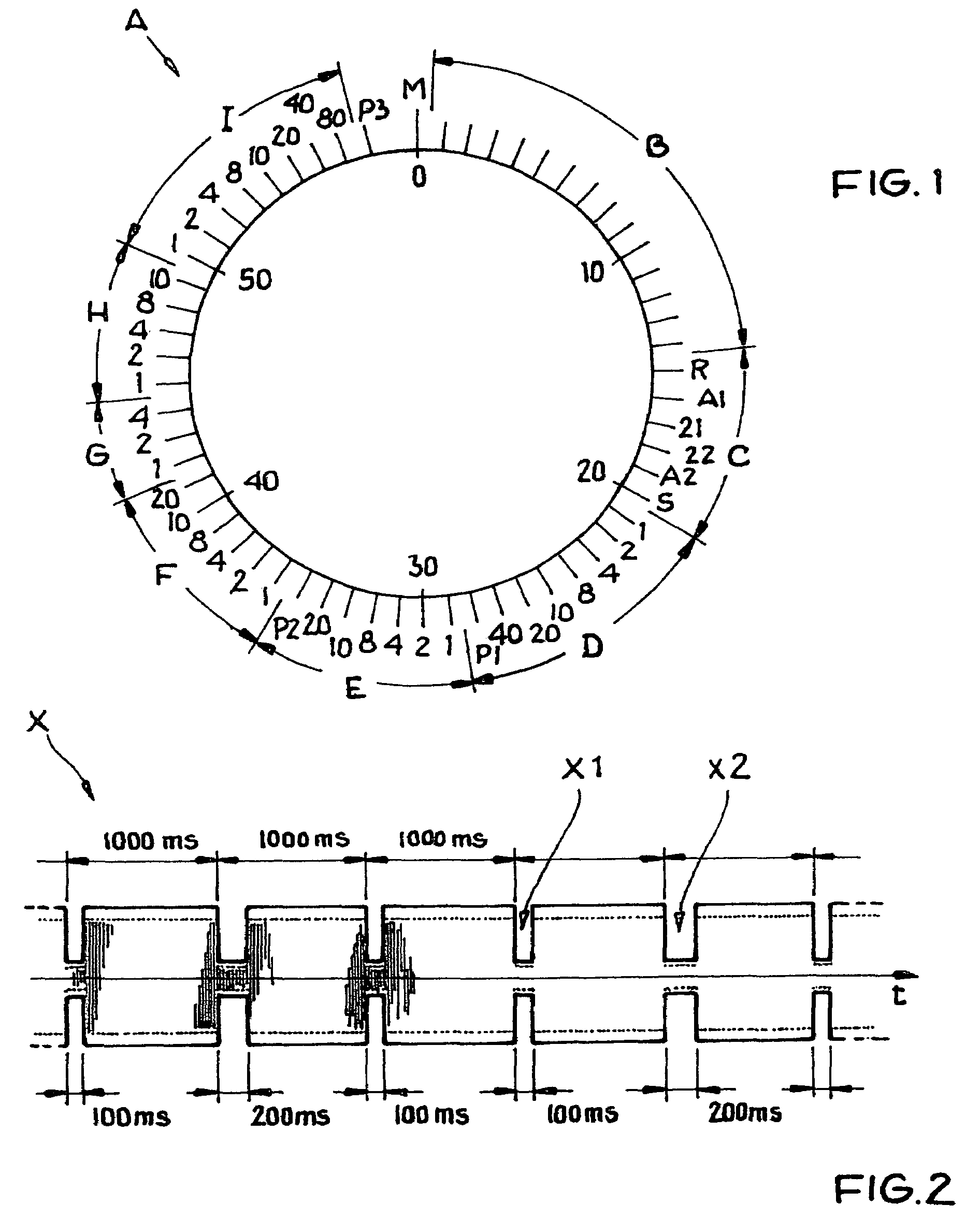
[0057]The general format of an encoding protocol of a time code telegram A as conventionally known in the time signal transmitted by the official German time signal transmitter DCF-77 has been explained above in the Background Information section. Similarly, the time-variation of the amplitude-modulated time signal is schematically shown in the time diagram of FIG. 2, which has been discussed above as well.

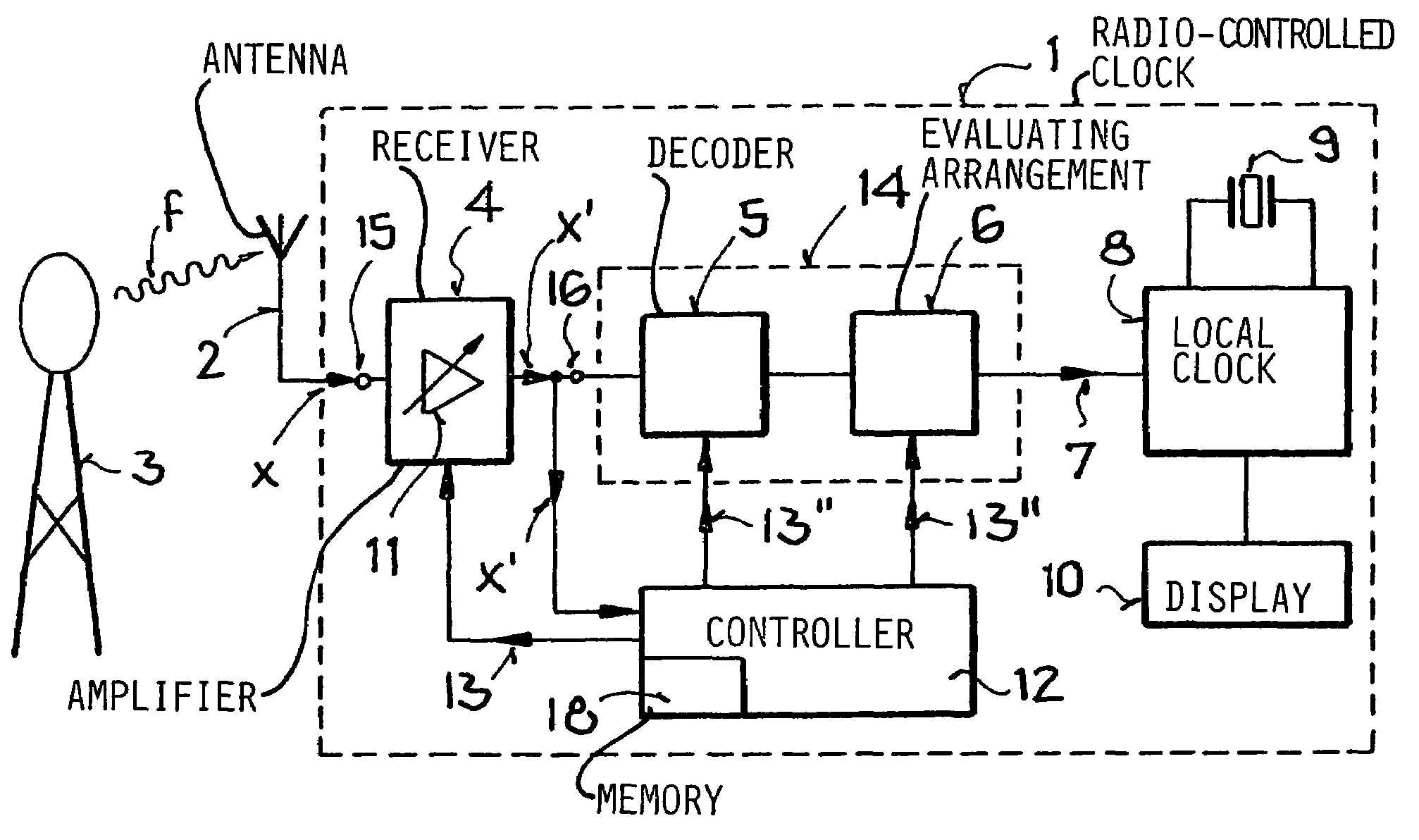
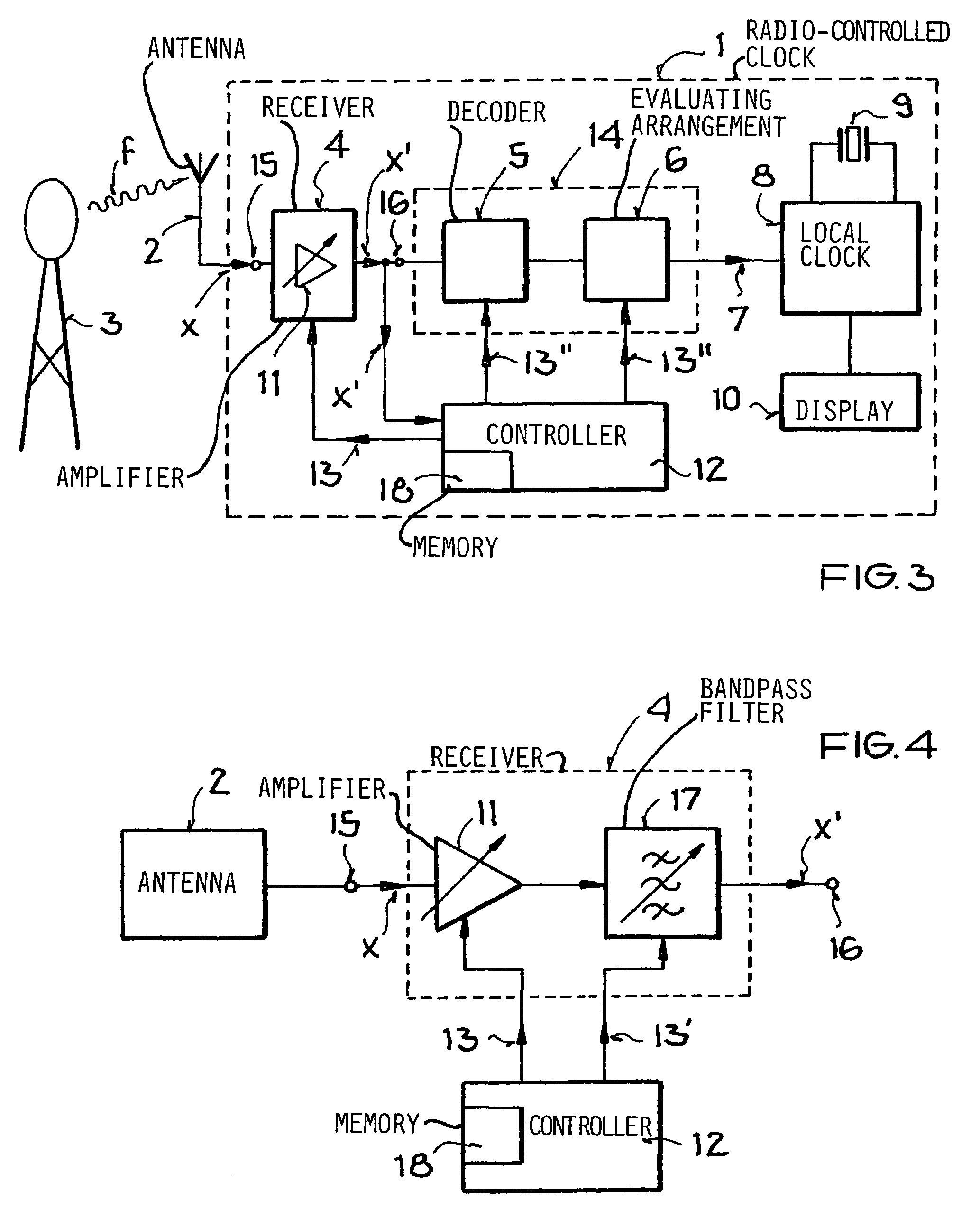
[0058]The block circuit diagram of FIG. 3 illustrates a first variant of a radio-controlled clock with adjustable amplification according to the invention. The radio-controlled clock 1 comprises one or more antennas 2 for receiving a time signal X transmitted by the time signal transmitter 3. The time signal X has a frequency f. The clock 1 further comprises a r...


PUM


Abstract

A time signal carrying encoded time information transmitted at a transmission frequency from any one of plural time signal transmitters is received, amplified, and evaluated to acquire the time information. The transmission frequency of the received time signal is determined (provided is the time information signal's just emitted frequency f), and an amplification factor of the amplification of the signal is adjusted depending on the transmission frequency. A receiver circuit for a radio-controlled clock in this regard includes at least one amplifier having a variable amplification factor that is adjustable dependent on the frequency of the received time signal.

Description

PRIORITY CLAIM[0001]This application is based on and claims the priority under 35 U.S.C. §119 of German Patent Application 103 57 200.7 filed on Dec. 8, 2003, and German Patent Application 10 2004 002 776.5 filed on Jan. 20, 2004, the entire disclosures of both of which are incorporated herein by reference.FIELD OF THE INVENTION[0002]The invention relates to a receiver circuit for a radio-controlled clock for receiving time signals transmitted from various different time signal transmitters, with an amplifier circuit for amplifying the received signals and a filter circuit for filtering the received signals. The invention further relates to a method of acquiring time information from the received time signal by means of such a receiver circuit, as well as a radio-controlled clock including such a receiver circuit.BACKGROUND INFORMATION[0003]It is conventionally known to provide time reference information in time signals that are transmitted by radio transmission from a time signal t...

Claims


Application Information

Patent Timeline
Patent Type & Authority Patents(United States)
IPC IPC(8): H04J3/06G04C11/02G04G5/00G04G21/04H04L12/50
CPCG04G5/002G04G21/04G04R20/10
Inventor KUEHNLE, JOACHIMPOLONIO, ROLANDSAILER, HANS-JOACHIM
Owner ATMEL CORP
Why Eureka
Try Eureka