
Method of controlling the transmitting power in a mobile radio system and corresponding mobile radio system

Inactive Publication Date: 2006-06-20
SIEMENS AG
View PDF9 Cites 8 Cited by
  • Summary
  • Abstract
  • Description
  • Claims
  • Application Information

AI Technical Summary

Benefits of technology

[0008]In light of the preceding background, an object of the present invention is to create an improved method of controlling the transmitting power in a mobile radio system. The present invention further provides a corresponding mobile radio system which eliminates the influence of delays in the power control system as completely as possible.
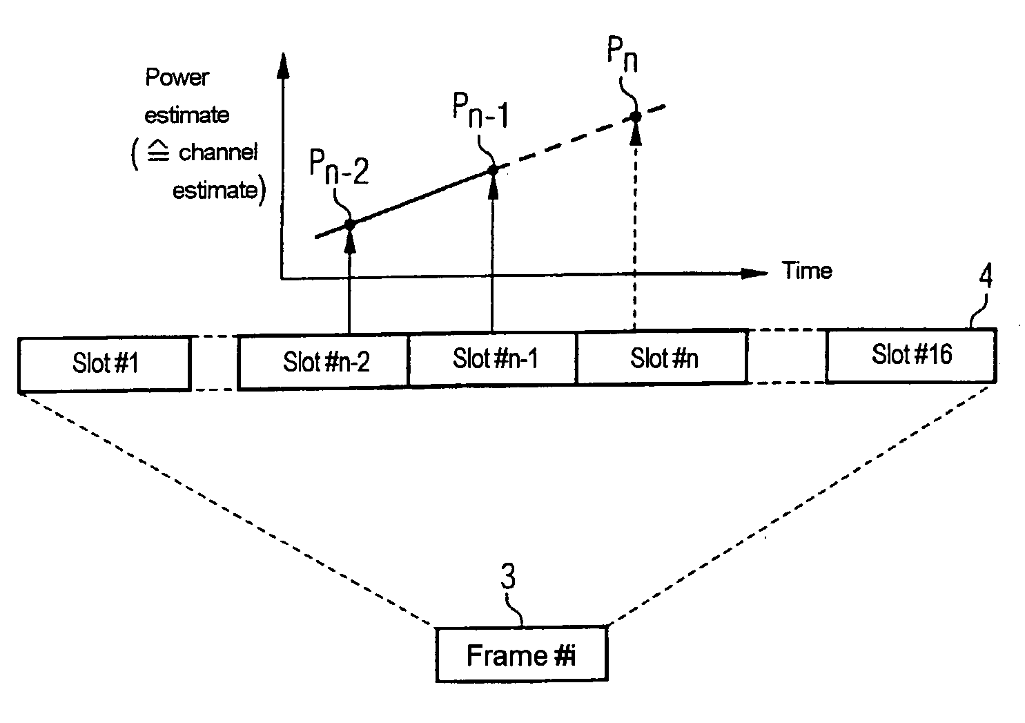
[0011]The step of estimating the behavior of the transmission channel involves estimating the behavior of the channel over time, as well as predicting a future state of the transmission channel. Thus, the transmitting power needed in the future can be calculated based on the estimated behavior and state of the transmission channel. In contrast to the known state of the art, the power control information which represents the basis for adjusting the transmitting power of the transmitter is not based on the instantaneous measured value of the received level or of the received quality of the transmit signal but on the above-described prediction of the channel state and the transmitting power needed in future. In this manner, the influence of delays can be eliminated in the control of the transmitting power if the behavior of the transmission channel can be predicted with sufficient accuracy. The behavior of the channel state can be estimated, for example, via the channel impulse response.

Problems solved by technology

However, employing this method, the transmitter can only react to the measurements of the receiver.
The inherent delay in waiting for the power information feedback signal from the receiver leads to a degradation of the transmission characteristic of the mobile radio system.
Such signal distortion renders information transmission impossible in the most extreme cases.

Method used


Image

  • Method of controlling the transmitting power in a mobile radio system and corresponding mobile radio system
  • Method of controlling the transmitting power in a mobile radio system and corresponding mobile radio system
  • Method of controlling the transmitting power in a mobile radio system and corresponding mobile radio system

Examples


Embodiment Construction

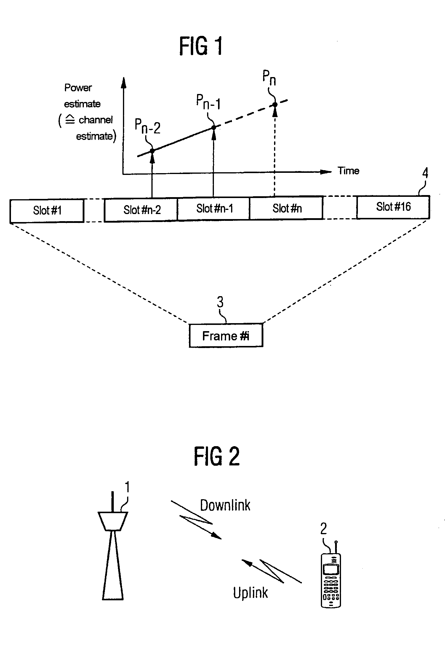
[0017]FIG. 2 shows the communication links between a base station 1 and a mobile radio station 2 of a mobile radio system. A connection from the base station 1 to the mobile part 2 is called the downlink or forward link connection and a connection from the mobile part 2 to the base station 1 is called the uplink or reverse link connection. To control the power of the downlink, the respective received signal is evaluated in the mobile station 2 and, depending on the result of the evaluation, a power control information item is generated by the mobile station 2 and sent back to the base station 1 so that the base station 1 can correspondingly adjust the transmitting power of the downlink. To control the uplink, the received signal is evaluated in the base station 1, where the power control information is generated and the mobile station 2 is instructed for power matching.

[0018]The power information item is transmitted in dependence on the respective mobile radio system linking with a ...


PUM


Abstract

A method is provided for controlling the transmitting power in a mobile radio system a corresponding mobile radio system is also provided. A signal emitted from a transmitter is received by a receiver via a transmission channel of the mobile radio system. The transmitted signal is evaluated and a power control information item is generated based on the result of the evaluation. The power control information item is then transmitted back to the transmitter for adjusting the transmitting power. In order to determine the power control information item, the time response of the transmission channel is estimated and the transmitting power needed in the future is deduced therefrom.

Description

BACKGROUND OF THE INVENTION[0001]The present invention relates to a method of controlling the transmitting power in a mobile radio system and to a corresponding mobile radio system.[0002]Controlling the transmitting power represents an important feature in mobile radio systems in order to prevent possible interference between individual connections. Preventing interference between connections improves the capacity and quality of the connections and allows the mean transmitting power to be reduced. Thus, the transmission power may be ideally adapted to the transmission requirements, and losses through the transmission channels may be at least partially compensated for.[0003]For the purpose of controlling the transmitting power in a mobile radio system, the signal transmitted by a transmitter is evaluated at the receiver. Power control information is generated based on the power of the received signal and is transmitted back to the transmitter. The transmitter may then adjust the tran...

Claims


Application Information

Patent Timeline
IPC IPC(8): H04M1/64H04B7/005
CPCH04W52/288H04W52/24H04W52/08
Inventor RAAF, BERNHARD
Owner SIEMENS AG
Learn More