Power transmission device and method for controlling same

Active Publication Date: 2020-03-12
AISIN AW CO LTD
View PDF0 Cites 2 Cited by
  • Summary
  • Abstract
  • Description
  • Claims
  • Application Information

AI Technical Summary

Benefits of technology

The patent is about a device that prevents the belt of a continuously variable transmission from slipping after the engine is stopped in response to deceleration of the vehicle. The device uses a sensor to detect the pressure of the belt and compares it to a threshold value to determine if enough clamping pressure can be obtained. By disengaging the hydraulic engagement element at the appropriate time, the device prevents the belt from slipping and ensures the vehicle can accelerate quickly when the engine is started again.

Problems solved by technology

However, the flow rate balance of a hydraulic system connected to the oil pump is likely to be influenced by variations in hardware, and the calculation accuracy of the number of revolutions of the engine deteriorates as the number of revolutions of the engine decreases.
Therefore, in the above-described conventional power transmission device, the belt of the continuously variable transmission mechanism may slip after the engine is stopped during coast traveling, which may reduce the durability of the belt.
Such a problem can likewise also occur in a case in which the operation of the engine is stopped when the vehicle speed of a vehicle having a belt type continuously variable transmission mechanism mounted thereon has been reduced to a predetermined vehicle speed.

Method used


Image

  • Power transmission device and method for controlling same
  • Power transmission device and method for controlling same
  • Power transmission device and method for controlling same

Examples


Embodiment Construction

[0014]Next, a mode for carrying out various aspects of the present disclosure will be described with reference to the drawings.

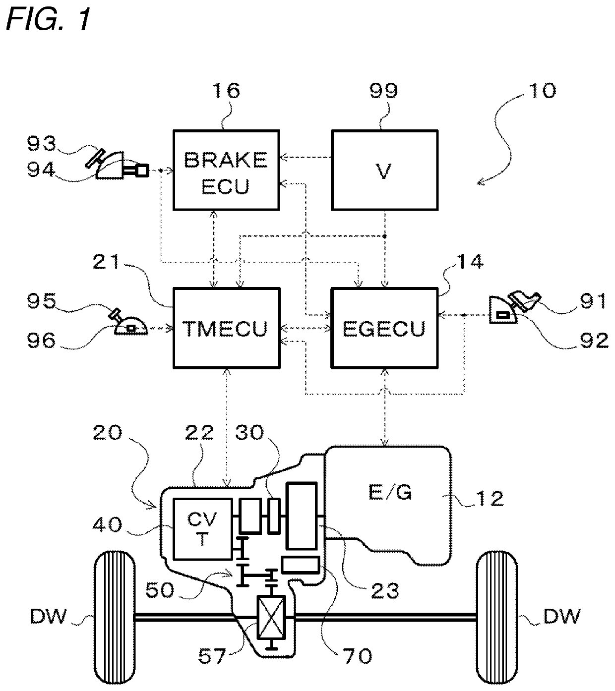
[0015]FIG. 1 is a schematic configuration diagram of a vehicle 10 having a power transmission device 20 of the present disclosure mounted thereon. The vehicle 10 shown in the drawing is a front-wheel-drive vehicle including an engine (internal combustion engine) 12 mounted on a vehicle's front portion, and includes an engine electronic control unit (hereinafter, referred to as “EGECU”) 14 that controls the engine 12, a brake electronic control unit (hereinafter, referred to as “brake ECU”) 16 that controls an electronically controlled hydraulic brake unit which is not shown, and a transmission electronic control unit (hereinafter, referred to as “TMECU”) 21 that controls the power transmission device 20, in addition to the power transmission device 20 that transmits power from the engine 12 to left and right drive wheels (front wheels) DW.

[0016]The EGECU 14 ...


PUM


Abstract

A power transmission device mounted on a vehicle in which operation of an engine is stopped when vehicle speed has been reduced to a predetermined vehicle speed. The device includes an oil pump driven by the engine; a hydraulic control device regulating pressure from the oil pump; a continuously variable transmission mechanism in which groove widths of a primary pulley and a secondary pulley are set by hydraulic pressure from the hydraulic control device; a hydraulic engagement element engaged by hydraulic pressure from the hydraulic control device to couple the continuously variable transmission mechanism to the engine; a clamping pressure sensor that detects clamping pressure of a belt of the continuously variable transmission mechanism; and a control device disengaging the hydraulic engagement element when the detected clamping pressure of the belt reaches less than or equal to a threshold value after operation of the engine is stopped.

Description

CROSS REFERENCE TO RELATED APPLICATIONS[0001]This application is a National Stage of International Application No. PCT / JP2018 / 019466, filed on May 21, 2018, which claims priority from Japanese Patent Application No. 2017-100634, filed on May 22, 2017.TECHNICAL FIELD[0002]The present disclosure relates to a power transmission device including an oil pump and a belt type continuously variable transmission mechanism which are driven by an engine mounted on a vehicle, and a method for controlling the power transmission device.BACKGROUND ART[0003]Conventionally, there is known a power transmission device including a belt type continuously variable transmission mechanism interposed between an engine and drive wheels; a clutch provided in a powertrain having the continuously variable transmission mechanism placed therein; a mechanical oil pump driven by the engine to supply hydraulic pressure to the clutch; and coast stop control means for stopping the engine when a predetermined start con...

Claims


Application Information

Patent Timeline
IPC IPC(8): B60W10/06B60W10/02F16H61/00F02D29/02F16H59/54F16H63/50
CPCF16H61/0031F16H63/50F16H59/54F02D29/02B60W10/02B60W10/06F16H59/48F16H59/74F16H61/662F02N11/0814F16H61/66272F16H59/72F16H2059/746F16H2312/14F02N11/0818F02N2200/0801
Inventor NOZAKI, MASAHIRO
Owner AISIN AW CO LTD
Why Eureka
Try Eureka