Communication apparatus

Active Publication Date: 2019-11-28
PEGATRON
View PDF1 Cites 0 Cited by
  • Summary
  • Abstract
  • Description
  • Claims
  • Application Information

AI Technical Summary

Benefits of technology

[0004]The application provides a communication apparatus capable of effectively preventing noise generated by a main circuit board

Problems solved by technology

However, because in part of the communication apparatuses, the metal shielding region of the top cover is distant from the system ground plane of the botto

Method used


Image

  • Communication apparatus
  • Communication apparatus
  • Communication apparatus

Examples


Example

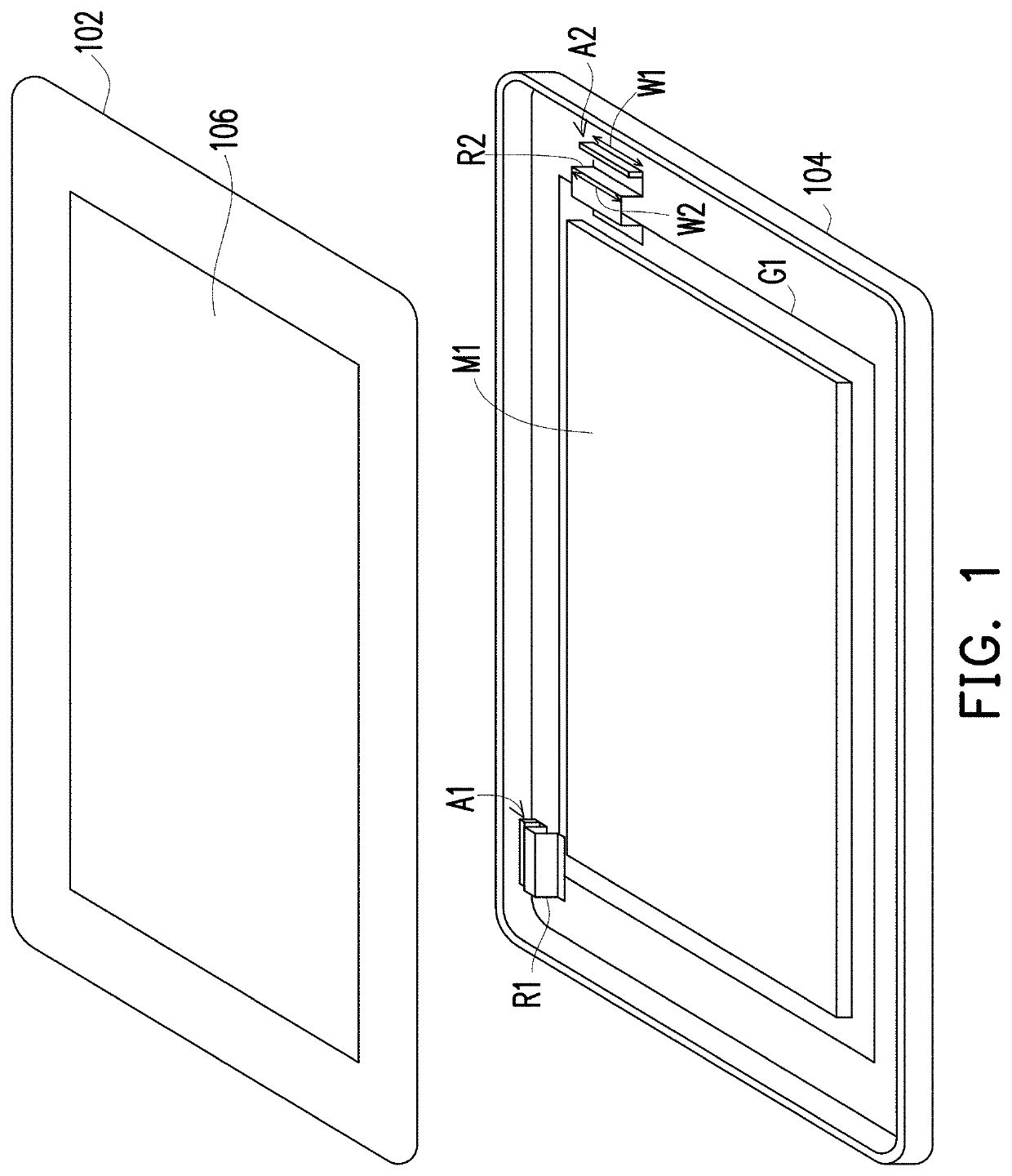
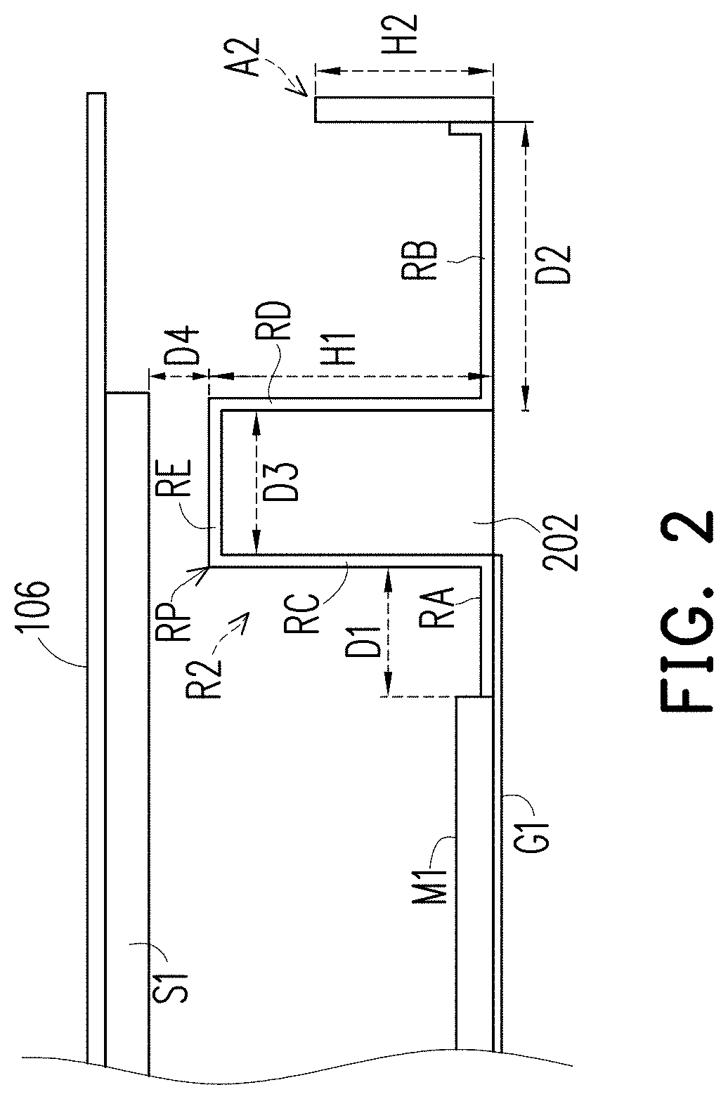
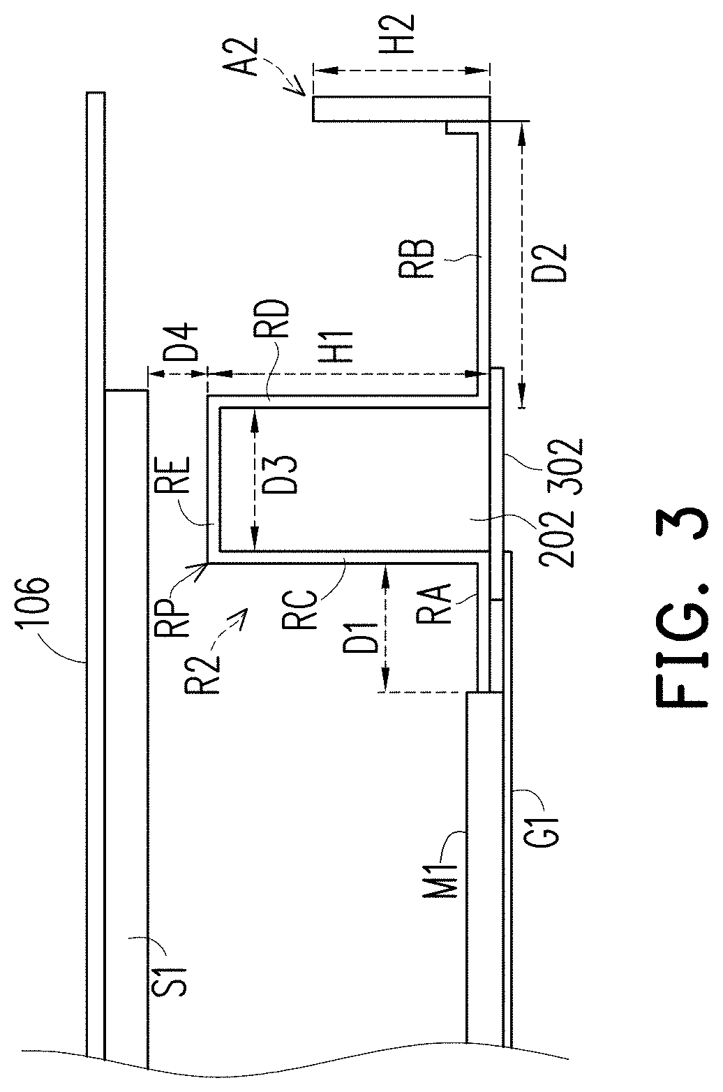
[0027]FIG. 1 is a schematic diagram illustrating a communication apparatus according to an embodiment of the application. Referring to FIG. 1, the communication apparatus may be, for example, a cell phone, a template computer or an all in one desktop computer, but the application is not limited thereto. The communication apparatus includes a top cover 102, a bottom cover 104, a display panel 106, a shielding metal plate S1 (referring to FIG. 2), a main circuit board M1, a ground plane G1, antennas A1 and A2 and retaining wall structures R1 and R2. When the top cover 102 is fastened to the bottom cover 104, a space included by the top cover 102 and the bottom cover 104 may be used to accommodate the display panel 106, the main circuit board M1, the ground plane G1, the antennas A1 and A2 and the retaining wall structures R1 and R2. The display panel 106 and the shielding metal plate S1 are disposed on the top cover 102, and the top cover 102 has an opening, such that when the display...


PUM


Abstract

A communication apparatus is provided. A retaining wall structure electrically connected with a ground plane is disposed between a main circuit board and an antenna. A retaining wall part of the retaining wall structure has a thickness. A distance between the retaining wall part and the main circuit board is a first distance, and a distance between the retaining wall part and the antenna and is a second distance. A distance between the retaining wall and a shielding metal plate is a third distance. The projection of the antenna projected toward the retaining wall in the orthogonal projection direction falls on the retaining wall part.

Description

CROSS-REFERENCE TO RELATED APPLICATION[0001]This application claims the priority benefit of Taiwan application serial no. 107118031, filed on May 25, 2018. The entirety of the above-mentioned patent application is hereby incorporated by reference herein and made a part of this specification.BACKGROUNDTechnical Field[0002]The application relates to an electronic apparatus and more particularly, to a communication apparatus.Description of Related Art[0003]Generally, an antenna of a wireless communication apparatus (for example, a notebook computer, a tablet computer or a cell phone . . . etc.) is usually disposed at a position opposite to a position of a screen. For example, the screen may be disposed on a top cover of the communication apparatus, and the antenna may be disposed on a bottom cover of the communication apparatus. Additionally, for the wireless communication apparatus to have preferable communication quality, a metal shielding region located on the top cover is connected...

Claims


Application Information

Patent Timeline
IPC IPC(8): H01Q1/52H05K5/00H05K9/00H01Q1/24H01Q1/22
CPCH01Q1/52H01Q1/526H01Q1/48H01Q1/243H01Q1/2266H04W88/02G06F1/1656G06F1/1698G06F1/1626H01Q1/528H05K5/0017H05K9/0054
Inventor WU, CHIEN-YICHANG, HUAN-CHIAWU, CHAO-HSUHUANG, SHIH-KENGTSAI, CHIA-CHOUCHU, YU-YI
Owner PEGATRON
Why Eureka
Try Eureka