
Thermal Snow and Ice Prevention System for Bridge Cables

Active Publication Date: 2019-11-28
AEF ICE SYST INC
View PDF0 Cites 5 Cited by
  • Summary
  • Abstract
  • Description
  • Claims
  • Application Information

AI Technical Summary

Benefits of technology

The patent is about a system and method for preventing snow and ice from accumulating on bridge cables. The system includes multiple heaters placed on the cables in a way that individual sections can be targeted for heating. The heaters are controlled by a control system that activates them in an order to prioritize areas that are at higher risk of falling snow or ice. The controllers can also direct power to specific heater sections to remove or prevent accumulation of snow or ice. The system helps to reduce the risk of accidents caused by falling snow and ice on the bridge cables.

Problems solved by technology

The top segments of each cable present the greatest risk for falling snow and ice since snow and ice falling from these locations has the furthest distance to fall.
The risk of falling snow and ice is a product of the time an accretion is in place and the likelihood that the falling accretion will cause damage.

Method used


Image

  • Thermal Snow and Ice Prevention System for Bridge Cables
  • Thermal Snow and Ice Prevention System for Bridge Cables
  • Thermal Snow and Ice Prevention System for Bridge Cables

Examples


Embodiment Construction

[0022]The present invention will be better understood with reference to the following description taken in combination with the drawings. For the purpose of illustration, there are shown in the drawings certain embodiments of the present invention. In the drawings, like numerals indicate like elements throughout. It should be understood, however, that the invention is not limited to the precise arrangements, dimensions, and instruments shown:

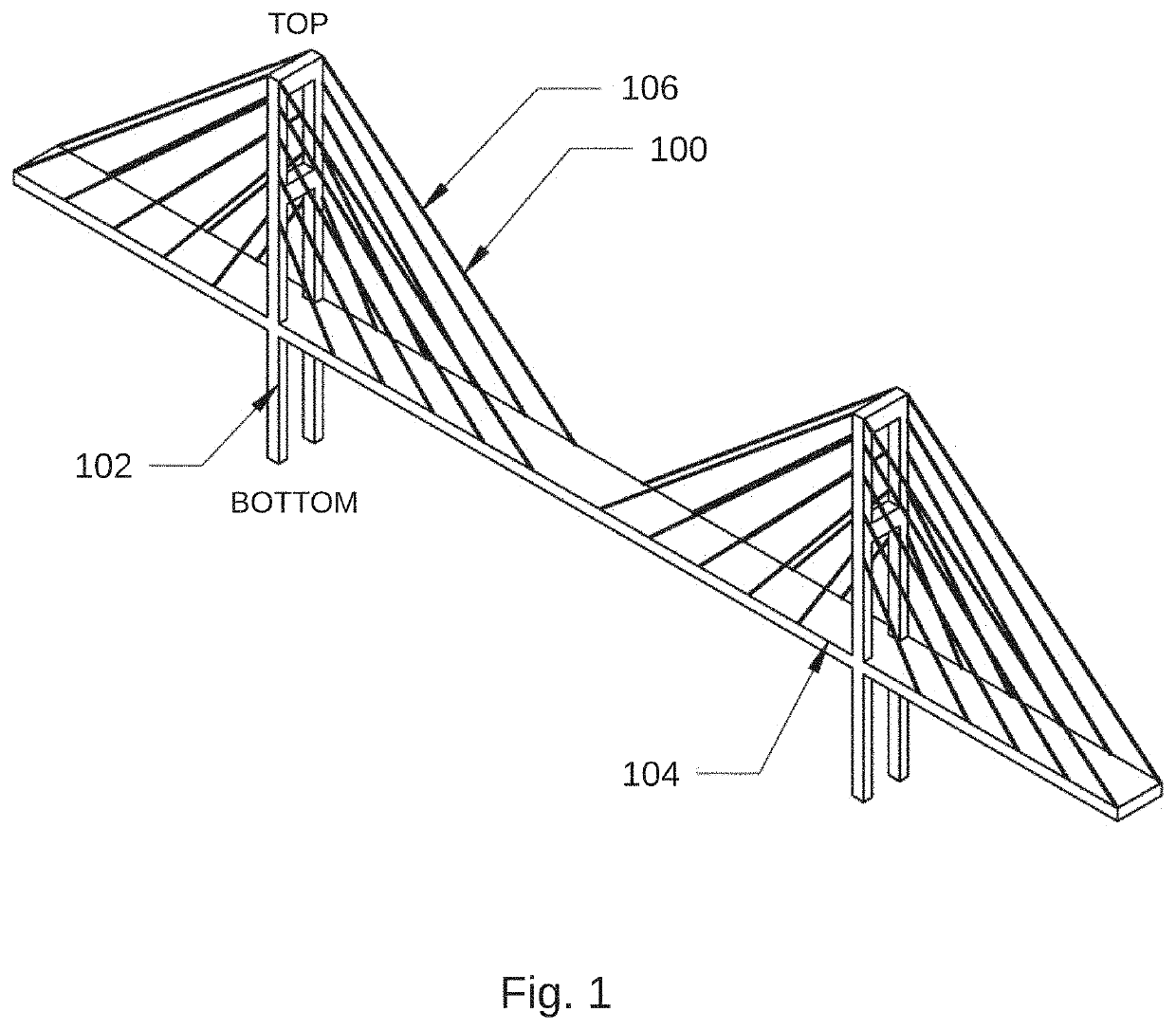
[0023]FIG. 1 illustrates an example of a cable stayed bridge containing a heating system;

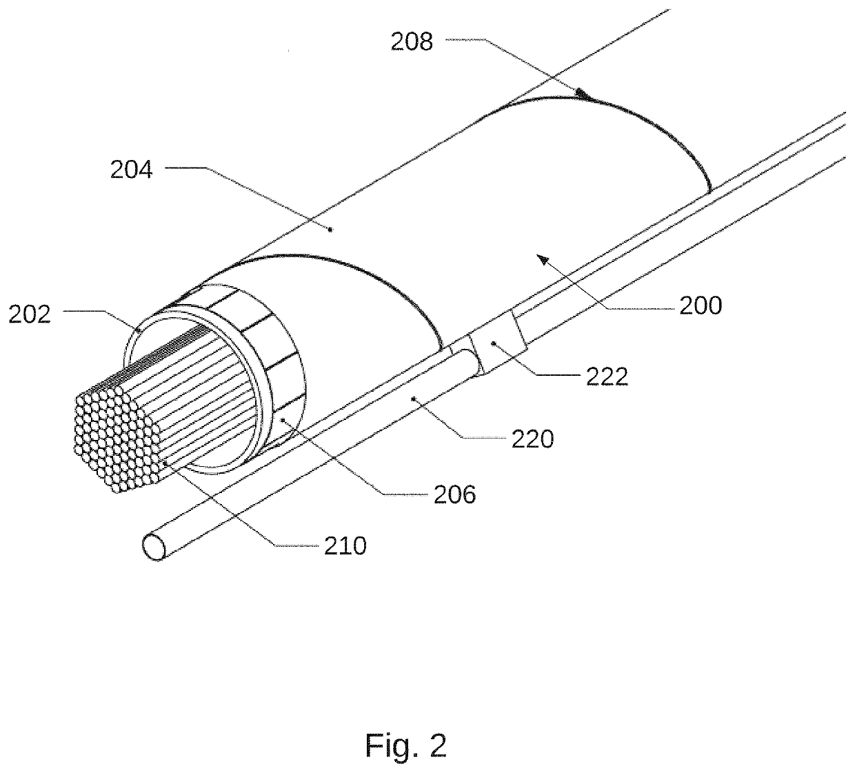
[0024]FIG. 2 illustrates a section view of an exemplary heated cable sheath;

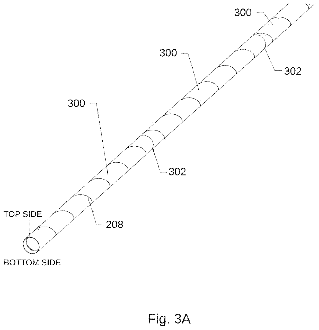
[0025]FIG. 3A illustrates an exemplary arrangement of several segments of a cable sheath;

[0026]FIG. 3B illustrates an exemplary arrangement of several segments of a cable sheath and the connection of heaters to form heating circuits;

[0027]FIG. 3C illustrates an example of the arrangement of heating circuits along a cable stay;

[0028]FIG. 4 illustrates an example of a heated half-sheat...


PUM


Abstract

Ice mitigation for bridge cables is provided by a system having a plurality of heaters on one or more bridge cables, extending parallel to a longitudinal axis thereof, arranged in a plurality of heater sections, and configured to heat an outer surface of the bridge cables, and a control system including one or more controllers configured to individually activate and regulate heating output of the heater sections to prevent snow or ice from falling from the bridge cables. The heater sections can be arranged radially, about a circumference of the bridge cables, and / or axially, end to end along a length of the bridge cables, so that power can be individually directed to the heater sections to account for differing heating requirements at different radial and / or axial aspects of the bridge cables.

Description

RELATED APPLICATIONS[0001]This application claims benefit of priority of: U.S. Provisional Application No. 62 / 676,362, filed May 25, 2018; and U.S. Provisional Application No. 62 / 676,350, filed May 25, 2018. Each of the above-identified related applications are incorporated herein by reference.FIELD OF THE INVENTION[0002]The present invention relates generally to thermal ice mitigation for bridge cables; and more particularly to a method and system providing anti-icing, de-icing, and / or intermittent de-icing of bridge cables.BACKGROUND OF THE INVENTION[0003]During winter storms, frozen precipitation can accumulate on cable-stayed bridges as wet snow, atmospheric icing, or freezing rain. During or after a storm the frozen accretion can shed off of the stay and ice can fall into traffic, damaging cars and injuring pedestrians. Several cable-stayed bridges have experienced significant icing problems resulting in injury, damage, and temporary bridge closure. Existing solutions are limit...

Claims


Application Information

Patent Timeline
IPC IPC(8): H02G7/16E01D19/16
CPCD07B1/147D07B5/002D07B2201/2088D07B2201/2089D07B2401/203D07B2501/203E01D19/16E01D11/04F25B2700/11F25D21/006F25D21/02F25D21/08H02G7/16
Inventor KUSTER, TRAVIS M.BROWN, ALEXANDER F.
Owner AEF ICE SYST INC
Learn More