

Fuel cell system
- Summary
- Abstract
- Description
- Claims
- Application Information
AI Technical Summary
Benefits of technology
Problems solved by technology
Method used
Image

Examples
first embodiment
A. First Embodiment
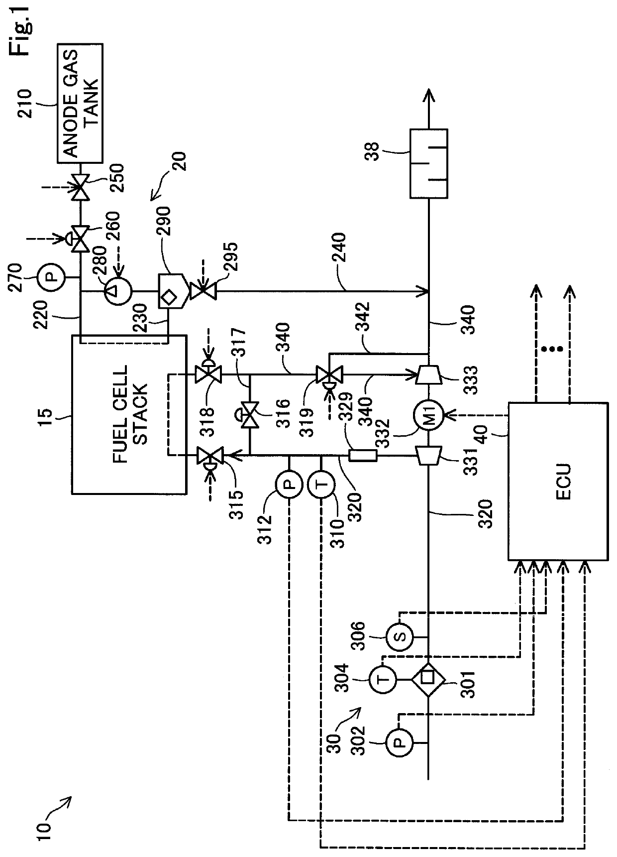
[0017]FIG. 1 is a schematic diagram illustrating a fuel cell system 10 in a first embodiment of the present disclosure. The fuel cell system 10 includes a fuel cell stack 15, an anode gas supply-discharge system 20, a cathode gas supply-discharge system 30 and an ECU 40 serving as a controller. The ECU 40 controls operations of the fuel cell system 10. The fuel cell stack 15 generates electric power through a chemical reaction between anode gas and cathode gas. The fuel cell system 10 is installed in a vehicle as a power source.
[0018]The anode gas supply-discharge system 20 includes an anode gas tank 210, an anode gas supply path 220, an anode gas circulation path 230, a main stop valve 250, a pressure control valve 260, a pressure sensor 270, a circulation pump 280, a gas-liquid separator 290, a gas-liquid discharge valve 295 and a gas-liquid discharge path 240.
[0019]The anode gas tank 210 stores high pressure hydrogen gas, for example. The anode gas tank 210 is ...
second embodiment
B. Second Embodiment
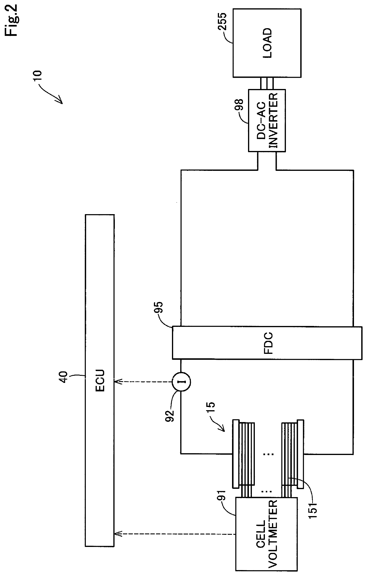
[0059]FIG. 8 is a conceptual diagram illustrating an electrical configuration of a fuel cell system 10a in a second embodiment of the present disclosure. Differences from the fuel cell system 10 in the first embodiment shown in FIG. 2 are that the fuel cell system 10a in this embodiment includes a secondary battery 96 and a BDC 97. In the description below, elements that are the same as those in the first embodiment are denoted with the same reference numerals as in the first embodiment, and the description thereof will be omitted. Note that the fuel cell system 10a in the second embodiment includes the anode gas supply-discharge system 20 and the cathode gas supply-discharge system 30 as in the first embodiment.
[0060]The secondary battery 96 is formed from a lithium ion battery and works as an auxiliary power supply. Moreover, the secondary battery 96 supplies the fuel cell stack 15 with electric power and takes in electric power generated by the fuel cell stack...
third embodiment
C. Third Embodiment
[0066]FIG. 10 is a schematic diagram illustrating a fuel cell system 10b in a third embodiment of the present disclosure. Differences from the fuel cell system 10 in the first embodiment shown in FIG. 1 are that the fuel cell system 10b in this embodiment includes a first compressor 331a driven by the motor M1 and a second compressor 331b on a downstream side of the first compressor 331a. In the description below, elements that are the same as those in the first embodiment are denoted with the same reference numerals as in the first embodiment, and the description thereof will be omitted. The first compressor 331a and the second compressor 331b are disposed on the cathode gas supply path 320.
[0067]The first compressor 331a is different from the compressor 331 of the first embodiment in that it is not connected to the turbine 333. The first compressor 331a includes the motor 332, and driving the motor 332 makes the first compressor 331a discharge the cathode gas do...
PUM
 Abstract
Description
Claims
Application Information