Uplink signal based handover control, handover cancellation and handover expiration

a technology of uplink signal and handover, applied in the direction of electrical equipment, wireless communication, etc., can solve the problems of unsatisfactory service, unsatisfactory handover, and inability to report measurements, so as to avoid adverse effects of measurement errors on handover, improve the measurement capability of base stations, and improve the effect of handover

Active Publication Date: 2019-12-12
SONY CORP
View PDF5 Cites 4 Cited by
  • Summary
  • Abstract
  • Description
  • Claims
  • Application Information

AI Technical Summary

Benefits of technology

[0006]According to an embodiment, a method of controlling communication in a wireless communication network is provided. According to the method, a wireless communication device receives a message from a base station, in the following also referred to as source base station. The message indicates authorization of a handover of the wireless communication device from the source base station to at least one candidate base station which is prepared to act as a target base station of the handover. In response to the message, the wireless communication device sends at least one uplink (UL) signal for measurements by the at least one candidate base station. In some cases, the at least one UL signal may also be used for measurements by the source base station. Depending on the measurements based on the UL signal the handover may then be controlled in a precise and efficient manner. Due to enhanced measurement capabilities of the base stations, adverse effects of measurement errors on the handover may be avoided. The measurements may for example be used for triggering the handover and / or for selecting one of the candidate base stations as the target base station of the handover. The measurements may for example be channel quality measurements.

Problems solved by technology

However, in some situations this way of initiating a handover may provide unsatisfactory results.
For example, due to limitations of the UE with respect to performing the channel quality measurements, the channel quality measurements performed by the UE may be subject to measurement errors, resulting in inappropriate triggering of a handover or inappropriate selection of a target base station of the handover.
Further, the reporting of measurements may fail for example due to fast movement of the UE.

Method used


Image

  • Uplink signal based handover control, handover cancellation and handover expiration
  • Uplink signal based handover control, handover cancellation and handover expiration
  • Uplink signal based handover control, handover cancellation and handover expiration

Examples


Embodiment Construction

[0121]In the following, exemplary embodiments of the invention will be described in more detail. It has to be understood that the following description is given only for the purpose of illustrating the principles of the invention and is not to be taken in a limiting sense. Rather, the scope of the invention is defined only by the appended claims and is not intended to be limited by the exemplary embodiments described hereinafter.

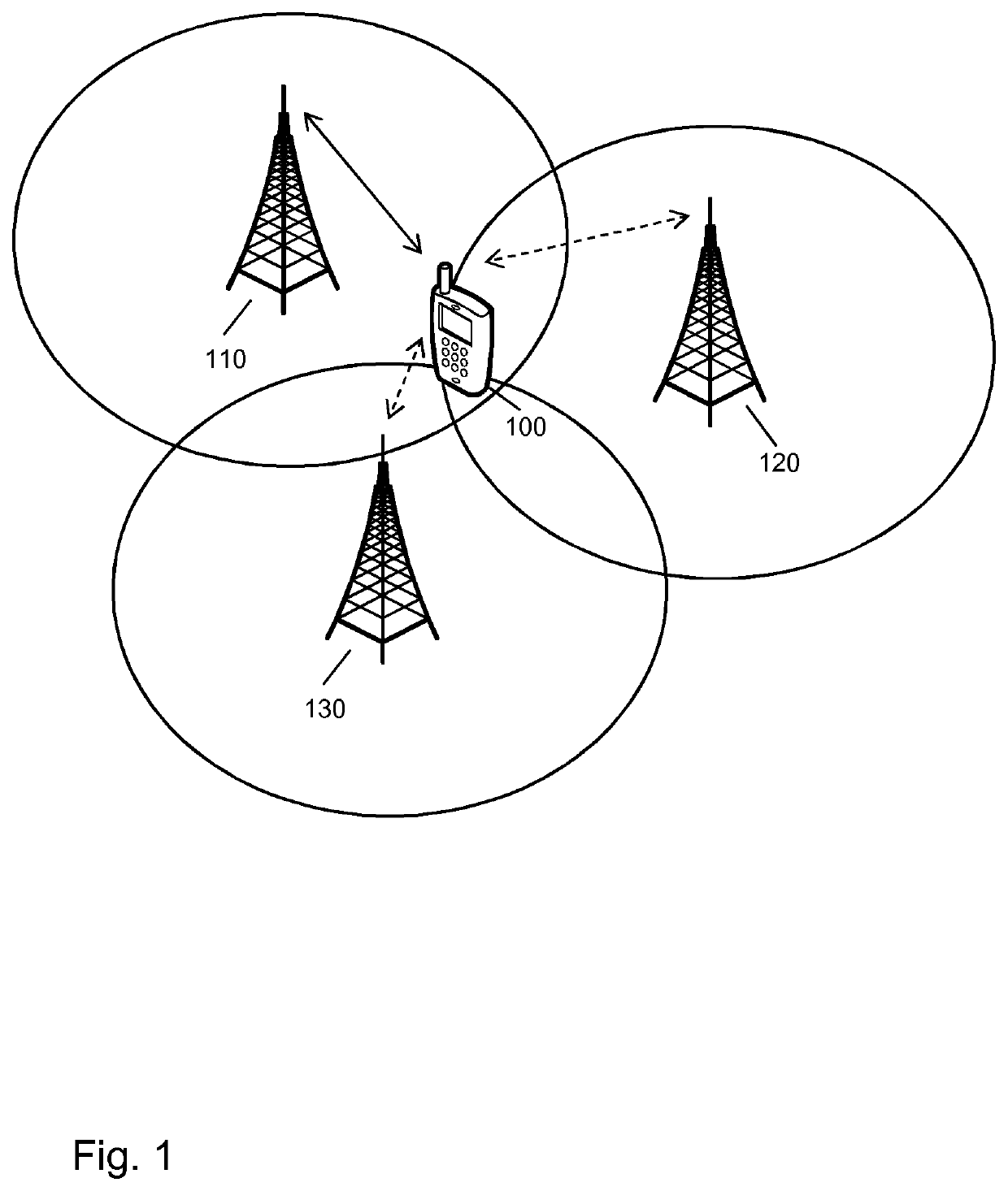
[0122]The illustrated embodiments relate to control of communication in a wireless communication network, in particular to control of a handover of a wireless communication device, in the following also referred to as UE, from a source base station to a target base station. By way of example, the wireless communication network may be based on the LTE radio technology specified by 3GPP or a 5G (5th Generation) radio technology, such as the NR (New Radio) technology currently developed by 3GPP. The wireless communication device may for example be a mobile phon...


PUM


Abstract

In a handover procedure of a wireless communication device (100), a source base station (110) of the handover sends a message to the wireless communication device (100). The message indicates authorization of a handover of the wireless communication device from the source base station to at least one candidate base station (120,130), which is prepared to act as a target base station of the handover. Further, the source base station (110) instructs the wireless communication device (100) to send at least one uplink signal. The source base station (110) receives at least one report of a measurement performed by the at least one candidate base station (120, 130) on the at least one uplink signal. Based on the at least one measurement, the source base station (110) controls the handover.

Description

FIELD OF THE INVENTION[0001]The present invention relates to methods of controlling communication in a wireless communication network and to corresponding devices and systems.BACKGROUND OF THE INVENTION[0002]Wireless communication networks, such as a cellular network based on the LTE (Long Term Evolution) radio technology specified by 3GPP (3rd Generation Partnership Project), mobility of a user equipment (UE) in the coverage area of the wireless communication network may involve that the UE performs a handover from one base station, referred to as source base station, to another base station, also referred as target base station.[0003]For example, when in LTE radio technology a UE is in connected mode, i.e., maintains an active data connection to the wireless communication network, it is typically configured to perform channel quality measurements on down-link (DL) reference signals from neighboring base stations and report such channel quality measurements in accordance with certa...

Claims


Application Information

Patent Timeline
Patent Type & Authority Applications(United States)
IPC IPC(8): H04W36/00H04W36/08H04W36/30H04W36/38
CPCH04W36/0016H04W36/30H04W36/08H04W36/385H04W36/0085H04W36/00835H04W36/00837
Inventor SHARMA, VIVEKWEI, YUXINMARTIN, BRIANWAKABAYASHI, HIDEJIBERGGREN, ANDERS
Owner SONY CORP
Why Eureka
Try Eureka