Joint component manufacturing method

a manufacturing method and joint technology, applied in the direction of rod connections, couplings, forging/pressing/hammering apparatus, etc., can solve the problems of further reducing bonding force and weakening bonding force between the first and the second members, so as to facilitate the fitting of the hole and reduce the occurrence of burrs.

Active Publication Date: 2019-12-19
FCC KK
View PDF4 Cites 0 Cited by
  • Summary
  • Abstract
  • Description
  • Claims
  • Application Information

AI Technical Summary

Benefits of technology

[0008]According to each aspect of the present invention configured as described above, in the joint component manufacturing method, the hole of the first member and the shaft portion of the second member are bonded to each other by press-fitting with the first strong press-fit interference and the second strong press-fit interference through press-fitting with the first weak press-fit interference and the second weak press-fit interference. In this case, the first weak press-fit interference and the second weak press-fit interference are, with respect to the first strong press-fit interference and the second strong press-fit interference, formed such that an overlapping thickness (i.e., the press-fit interference) between both members is decreased. Thus, according to the joint component manufacturing method of the present invention, occurrence of burrs upon bonding between the first member having the hole and the second member having the shaft portion can be reduced while close contact between both members without any clearances and firm bonding between both members can be realized.
[0010]According to the other aspect of the present invention configured as described above, in the joint component manufacturing method, the first weak press-fit interference and the second weak press-fit interference are formed to such a thickness that no burrs are generated between the first member and the second member fitted to each other. Thus, occurrence of burrs upon bonding between the first member having the hole and the second member having the shaft portion can be more effectively reduced. In this case, the first weak press-fit interference and the second weak press-fit interference are set for each of the materials, shapes, and press-fit conditions of the first member and the second member, and therefore, are obtained by experiment in advance. Note that a burr is one generated when part of the material forming the hole and / or the shaft portion is carved or extruded to the periphery of an opening of the hole upon fitting between the hole and the shaft portion in a press-fit state.
[0012]According to the other aspect of the present invention configured as described above, the guide portion having the inclined surface or the curved surface is formed at at least one corner portion of the tip end portions first fitted to each other upon fitting between the hole and the shaft portion. Thus, the shaft portion of the second member is smoothly guided to the hole of the first member, and is easily fitted in the hole. Thus, occurrence of burrs can be more effectively reduced.
[0014]According to the other aspect of the present invention configured as described above, in the joint component manufacturing method, the weak press-fit portion has the gradually-changing portion of which the shape gradually changes with respect to the strong press-fit portion. Thus, the shaft portion of the second member is smoothly guided to the hole of the first member, and is easily fitted in the hole. Thus, occurrence of burrs can be more effectively reduced.

Problems solved by technology

Thus, there are problems that bonding force between the first member and the second member is weakened and such bonding force is further decreased due to a clearance in the burr housing portion in a case where the amount of burrs entering the burr housing portion is small.

Method used


Image

  • Joint component manufacturing method
  • Joint component manufacturing method
  • Joint component manufacturing method

Examples


first embodiment

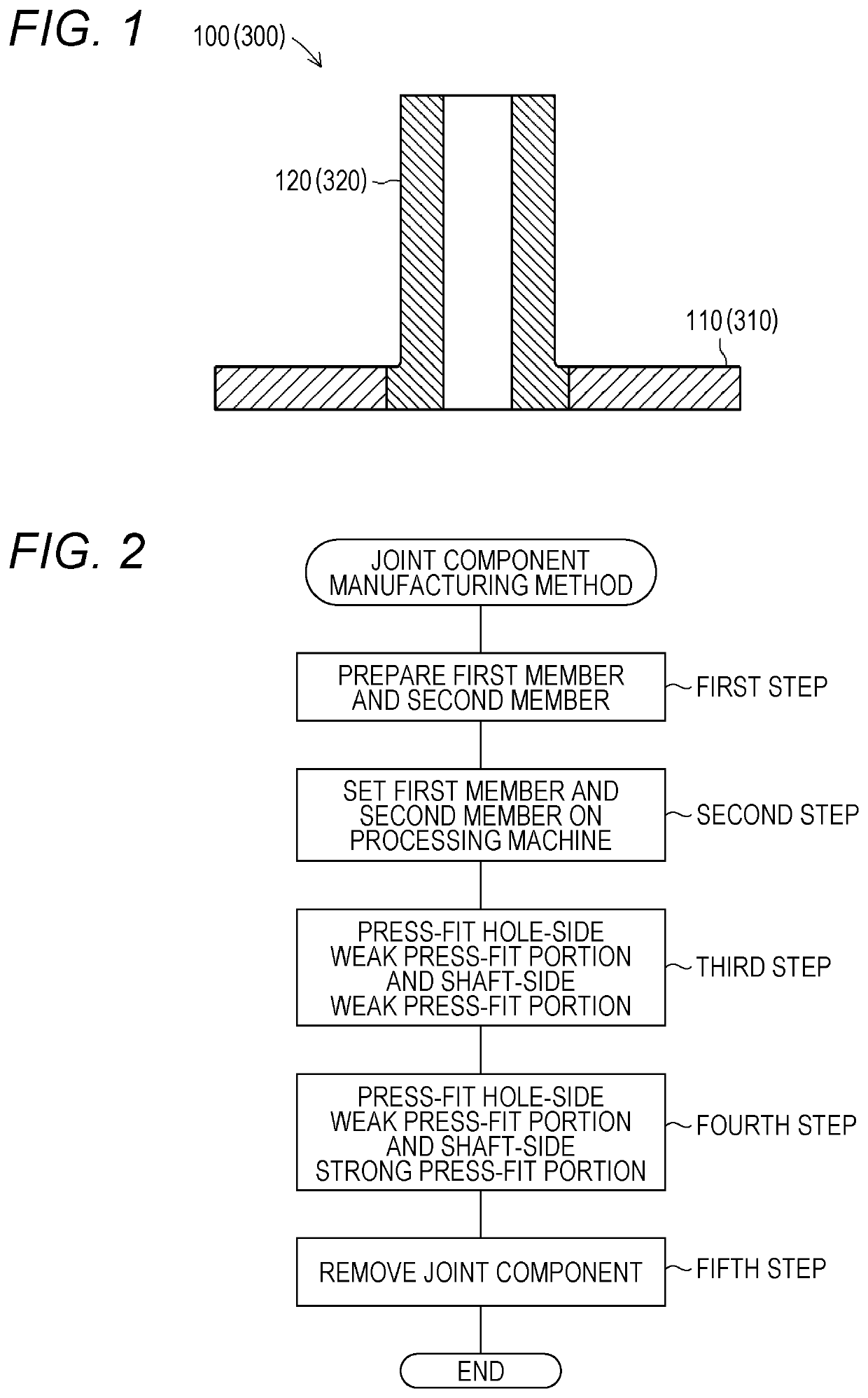
[0030]Hereinafter, a first embodiment of a joint component manufacturing method according to the present invention will be described with reference to the drawings. FIG. 1 is a schematic sectional view of an outline configuration of a joint component 100 formed by the joint component manufacturing method according to the present invention. Moreover, FIG. 2 is a flowchart of the flow of main steps in the method for manufacturing the joint component 100 according to the first embodiment of the present invention. Note that for the sake of easy understanding of the present invention, each figure referred in the present specification is schematically illustrated, and for example, some components are exaggeratingly illustrated. Thus, the dimensions and ratio of each component may be changed.

[0031]First, the joint component 100 formed by the joint component manufacturing method according to the present invention will be briefly described. The joint component 100 mainly includes a first mem...

second embodiment

[0060]Next, a second embodiment of a joint component manufacturing method according to the present invention will be described with reference to FIGS. 8 to 11. In the second embodiment, differences from the first embodiment will be mainly described.

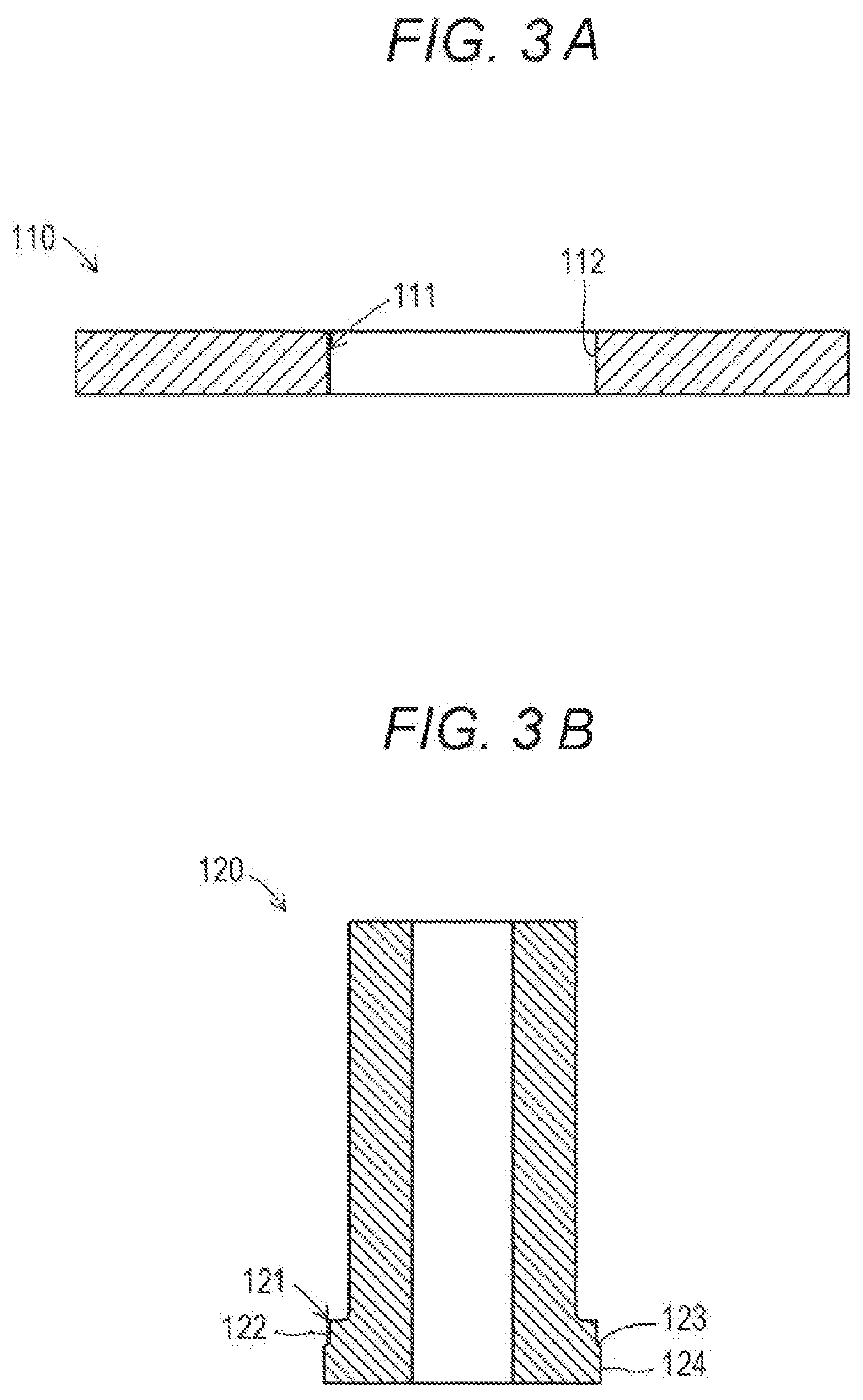
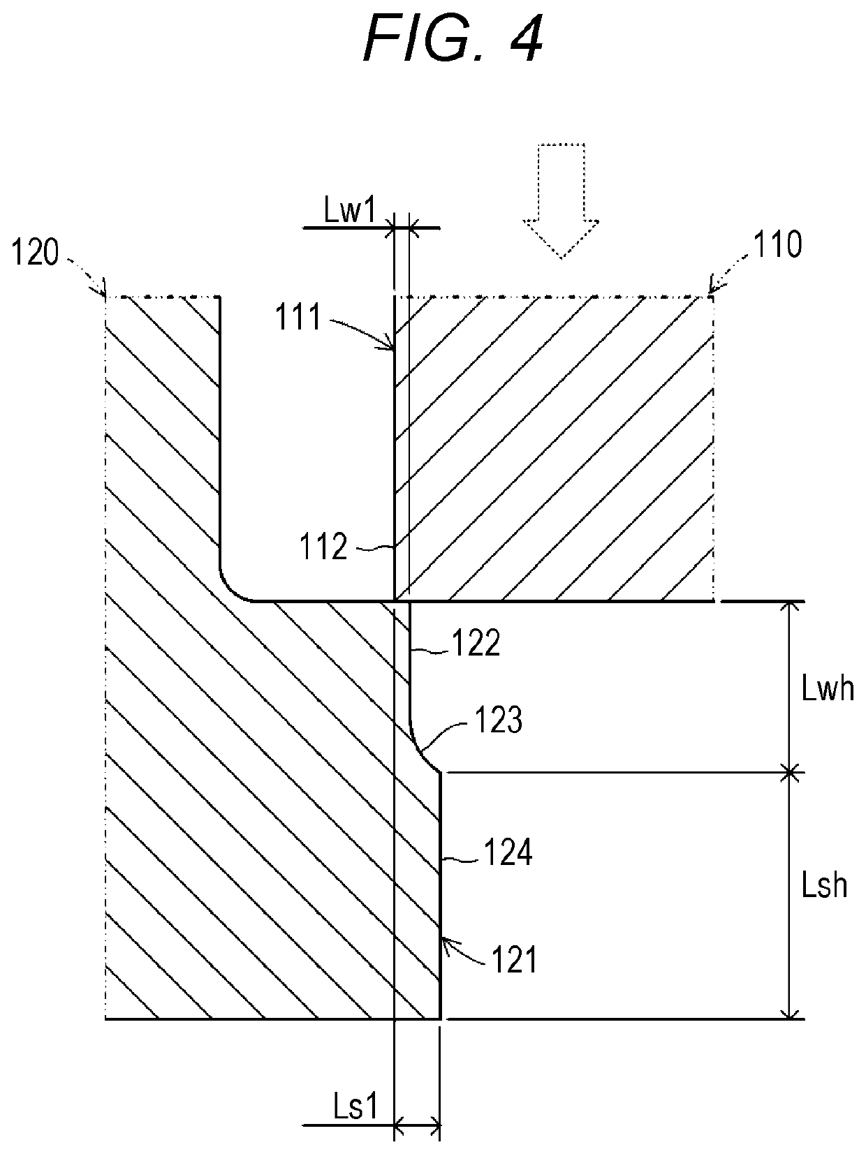
[0061]A joint component 300 configured in a manner similar to that of the joint component 100 mainly includes a first member 310 and a second member 320. In the first member 310, each of a hole-side weak press-fit portion 312, a gradually-changing portion 313, and a hole-side strong press-fit portion 314 is formed at a through-hole-shaped hole 311. Moreover, the second member 320 is configured such that each of a shaft-side weak press-fit portion 322, a gradually-changing portion 323, and a shaft-side strong press-fit portion 324 is formed at a cylindrical shaft portion 321.

[0062]As illustrated in FIG. 9, the hole-side weak press-fit portion 312 and the shaft-side weak press-fit portion 322 are portions formed with a second weak press-fit...


PUM

PropertyMeasurementUnit
diameteraaaaaaaaaa
diameteraaaaaaaaaa
diameteraaaaaaaaaa

Abstract

Provided is a joint component manufacturing method for reducing occurrence of burrs upon bonding between a first member having a hole and a second member having a shaft portion and firmly bonding both members. In the method for manufacturing a joint component 100, a hole-side weak press-fit portion 112 is formed at a hole 111 of a flat plate ring-shaped first member 110. Moreover, each of a shaft-side weak press-fit portion 122 and a shaft-side strong press-fit portion 124 is formed at a shaft portion 121 of a cylindrical second member 120. The hole-side weak press-fit portion 112 and the shaft-side weak press-fit portion 122 are defined by a first weak press-fit interference Lw1 formed thinner than a first strong press-fit interference Ls1. The shaft-side strong press-fit portion 124 is defined by a first strong press-fit interference Ls1 as the minimum necessary press-fit interference for electric resistance welding upon electric resistance welding between the hole 111 and the shaft portion 121.

Description

TECHNICAL FIELD[0001]The present invention relates to a joint component manufacturing method for joining a first member and a second member by fitting of a shaft portion of the second member in a hole of the first member.BACKGROUND ART[0002]Typically, there has been a joint component manufacturing method for joining a first member and a second member by fitting of a shaft portion of the second member in a hole of the first member. For example, in a press-fit bonding structure disclosed in Patent Literature 1 below, a burr housing portion configured to house burrs generated upon press-fitting is formed in the vicinity of an end portion of a bonding interface at which a hole of a first member and a shaft portion of a second member are fitted to each other.CITATION LISTPatent Literature[0003]PATENT LITERATURE 1: JP-A-2005-14064SUMMARY OF THE INVENTION[0004]However, in the press-fit bonding structure described in Patent Literature 1 above, the burr housing portion is formed continuously...

Claims


Application Information

Patent Timeline
Patent Type & Authority Applications(United States)
IPC IPC(8): B21D39/03F16B7/20B23K20/02F16B9/00F16B4/00B23P11/02B23K11/02
CPCF16B4/004B23P11/02F16B9/00B21D39/037B23K11/02F16B7/20B23K20/02B23P19/02B23P19/12B23P11/00B21K25/00B23K33/006B23K11/002B23K11/16B23K11/34B23K11/36B23K2101/04B23K2103/04F16D1/068F16B4/00B23K20/00B21D39/00
Inventor YAMAMOTO, HIROSHIKISE, TSUYOSHIMATSUNO, HIROYUKI
Owner FCC KK
Why Eureka
Try Eureka