Turbine wheel
a turbine wheel and rotor technology, applied in the manufacture of engines, blade accessories, machines/engines, etc., can solve the problems of residual tensile stress cracks, deterioration of overall efficiency of gas turbines, and reduced combustion gas flow rate to drive turbine rotors
- Summary
- Abstract
- Description
- Claims
- Application Information
AI Technical Summary
Benefits of technology
Problems solved by technology
Method used
Image
Examples
first embodiment
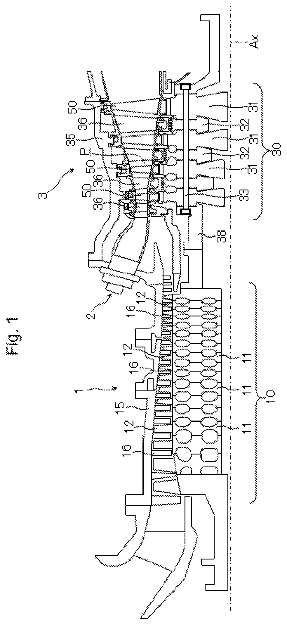
[0026]First, the configuration of a gas turbine including a turbine wheel according to a first embodiment of the present invention is explained by using FIG. 1. FIG. 1 is a longitudinal cross-sectional view illustrating the gas turbine including the turbine wheel according to the first embodiment of the present invention, in a state in which a lower half section of the gas turbine is omitted.
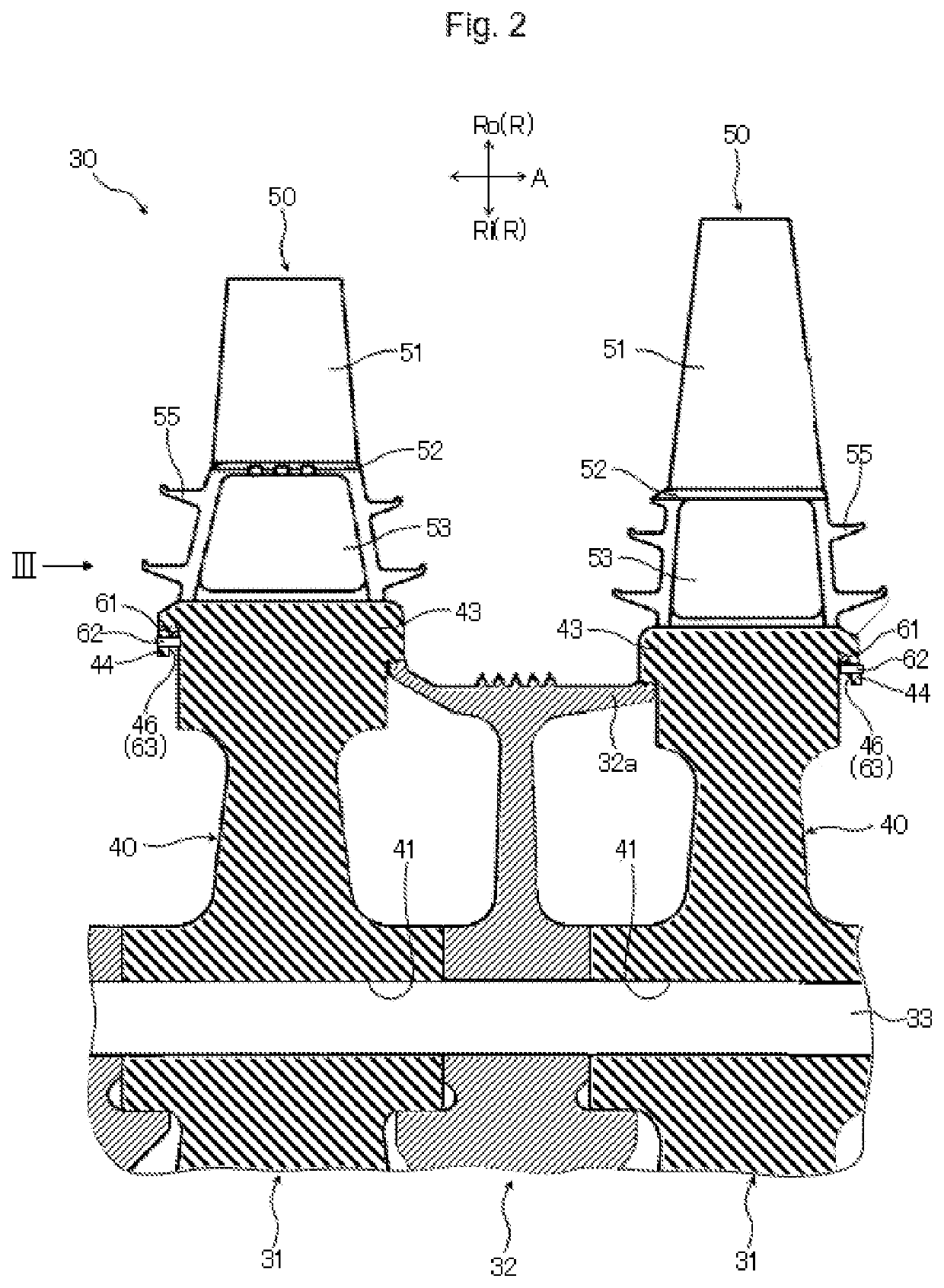
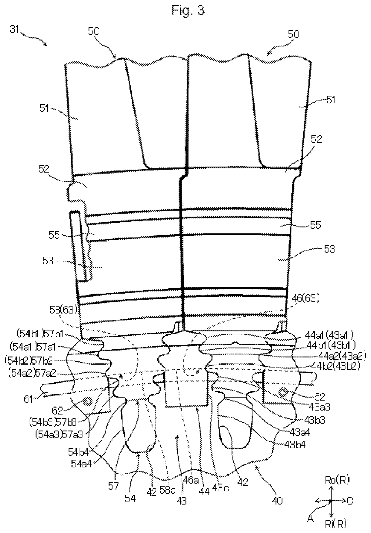
[0027]In FIG. 1, the gas turbine includes: a compressor 1 that compresses air that has been taken in, and generates compressed air; a combustor 2 that mixes the compressed air generated by the compressor 1 with fuel from a fuel system (not illustrated), and combusts the mixture to generate a combustion gas; and a turbine 3 that is rotation-driven by the high-temperature and high-pressure combustion gas generated at the combustor 2. The gas turbine has a multi-can type combustor, for example, and in the multi-can type, a plurality of combustors 2 are arrayed annularly at intervals in the circumfe...
second embodiment
[0077]Next, a turbine wheel according to a second embodiment of the present invention is explained by using FIG. 9. FIG. 9 is an explanatory diagram illustrating the outline shapes of wheel-side tab sections of the turbine wheel in the second embodiment of the present invention when seen in the axial direction. Note that portions in FIG. 9 that are given the same reference characters as those illustrated in FIG. 1 to FIG. 8 are similar portions, and thus detailed explanations thereof are omitted.
[0078]A difference of the turbine wheel according to the second embodiment of the present invention illustrated in FIG. 9 from the first embodiment lies in the outline shapes of wheel-side tab sections 44A. In the turbine wheel 40 of the first embodiment, the outline shape of the wheel-side tab section 44 when seen in the axial direction A has straight portions 44c along the predetermined straight lines Lc1 only in a portion on the radially inward side Ri of the bottom surface 46a of the sec...
third embodiment
[0085]Next, a turbine wheel according to a third embodiment of the present invention is explained by using FIG. 10. FIG. 10 is an explanatory diagram illustrating outline shapes of wheel-side tab sections of the turbine wheel in the third embodiment of the present invention when seen in the axial direction. Note that portions in FIG. 10 that are given the same reference characters as those illustrated in FIG. 1 to FIG. 9 are similar portions, and thus detailed explanations thereof are omitted.
[0086]A difference of the turbine wheel according to the third embodiment of the present invention illustrated in FIG. 10 from the second embodiment lies in outline shapes of wheel-side tab sections 44B. In the turbine wheel 40A of the second embodiment, the outline shape of the wheel-side tab section 44A when seen in the axial direction A has straight portions 44c1 and 44c2 along the predetermined straight lines Lc1 (see FIG. 9). In contrast, in a turbine wheel 40B of the third embodiment, the...
PUM
 Abstract
Description
Claims
Application Information
 - R&D
- Intellectual Property
- Life Sciences
- Materials
- Tech Scout
- Unparalleled Data Quality
- Higher Quality Content
- 60% Fewer Hallucinations
Browse by: Latest US Patents, China's latest patents, Technical Efficacy Thesaurus, Application Domain, Technology Topic, Popular Technical Reports.
© 2025 PatSnap. All rights reserved.Legal|Privacy policy|Modern Slavery Act Transparency Statement|Sitemap|About US| Contact US: help@patsnap.com


