Turbine Wheel

a turbine wheel and rotor technology, applied in the field of turbine wheels, can solve the problems of deteriorating overall efficiency of the gas turbine, affecting the operation of the turbine, and reducing the flow rate of combustion gas to drive the turbine rotor by a corresponding amount, so as to prevent local occurrence of excessive stress and occurrence of residual tensile stress

Active Publication Date: 2021-08-12
MITSUBISHI HEAVY IND LTD
View PDF0 Cites 0 Cited by
  • Summary
  • Abstract
  • Description
  • Claims
  • Application Information

AI Technical Summary

Benefits of technology

[0013]According to the present invention, an annular fixation wire is pressed almost uniformly against continuous bottom surfaces of first grooves and the second grooves due to the action of the centrifugal force at the time of the rotation of a turbine rotor. Accordingly, it is possible to prevent local occurrences of excessive stresses on the fixation wire. In addition, the outline shape of the wheel-side tab section when seen in the axial direction is such that at least part of projecting portions are removed from a wheel-side tab section of a conventional turbine wheel. Accordingly, it is possible to inhibit the wheel-side tab section from getting caught by a blade root section or a blade-side tab section of a turbine rotor blade when the turbine rotor blade is assembled onto or disassembled from the turbine wheel. Accordingly, occurrences of residual tensile stresses on the turbine wheel due to contact between turbine rotor blades and the wheel-side tab sections can be suppressed.

Problems solved by technology

Accordingly, if the flow rate of the cooling air is increased, the flow rate of the combustion gas to drive the turbine rotor decreases by a corresponding amount, and thus the overall efficiency of the gas turbine deteriorates.
It should be noted however that there is a concern over occurrences of cracks resulting from residual tensile stresses if parts formed of a Ni based alloy material are used in a high-temperature environment in a state in which they are receiving the residual tensile stresses.
This may cause residual tensile stresses at base portions of the lock tabs.
Accordingly, when a Ni based alloy is applied to the turbine wheel with a configuration like the one described in JP-2011-21605-A, there is a concern over occurrences of cracks in the turbine wheel resulting from residual tensile stresses caused by the interference of the turbine rotor blades with the lock tabs of the turbine wheel at the time of assembly or disassembly of the turbine rotor blades.

Method used


Image

  • Turbine Wheel
  • Turbine Wheel
  • Turbine Wheel

Examples


first embodiment

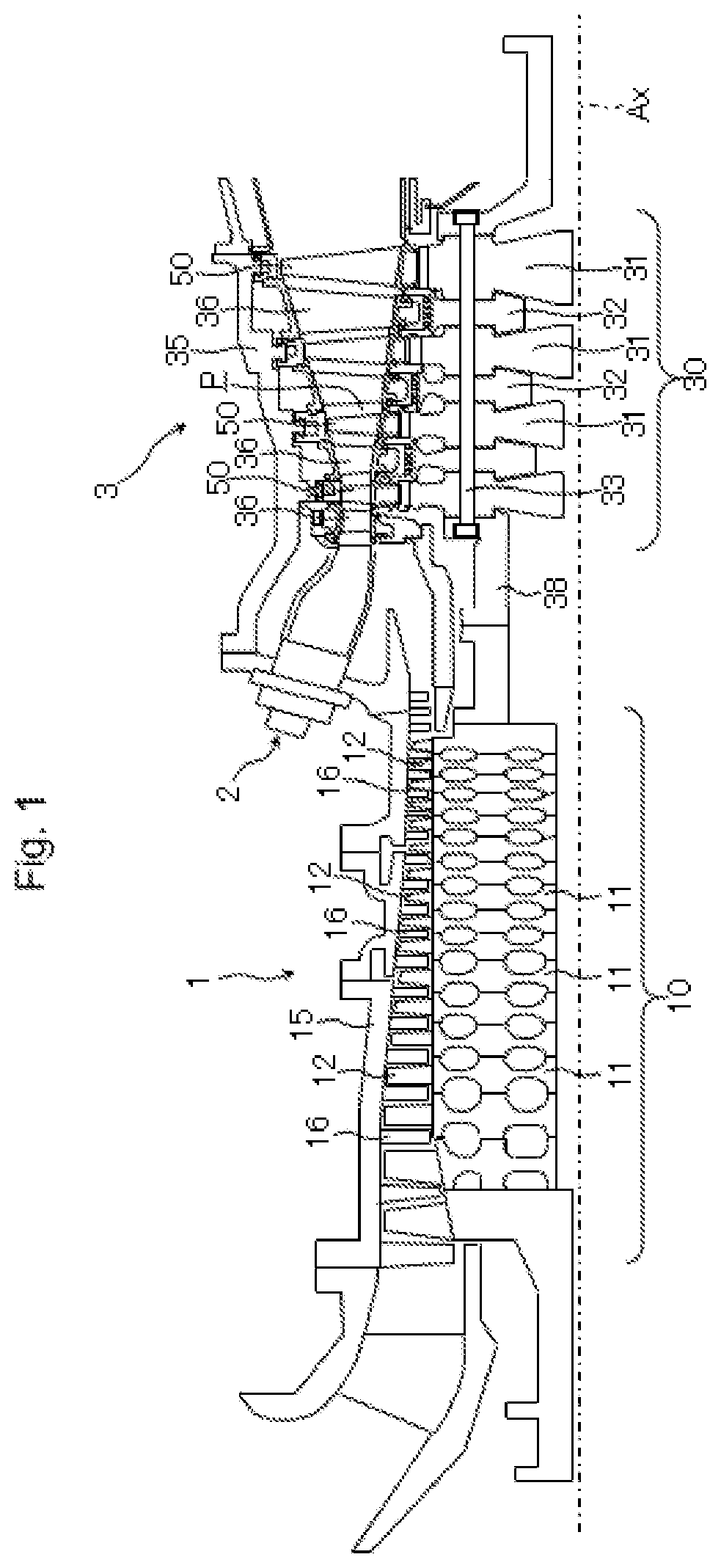
[0026]First, the configuration of a gas turbine including a turbine wheel according to a first embodiment of the present invention is explained by using FIG. 1. FIG. 1 is a longitudinal cross-sectional view illustrating the gas turbine including the turbine wheel according to the first embodiment of the present invention, in a state in which a lower half section of the gas turbine is omitted.

[0027]In FIG. 1, the gas turbine includes: a compressor 1 that compresses air that has been taken in, and generates compressed air; a combustor 2 that mixes the compressed air generated by the compressor 1 with fuel from a fuel system (not illustrated), and combusts the mixture to generate a combustion gas; and a turbine 3 that is rotation-driven by the high-temperature and high-pressure combustion gas generated at the combustor 2. The gas turbine has a multi-can type combustor, for example, and in the multi-can type, a plurality of combustors 2 are arrayed annularly at intervals in the circumfe...

second embodiment

[0077]Next, a turbine wheel according to a second embodiment of the present invention is explained by using FIG. 9. FIG. 9 is an explanatory diagram illustrating the outline shapes of wheel-side tab sections of the turbine wheel in the second embodiment of the present invention when seen in the axial direction. Note that portions in FIG. 9 that are given the same reference characters as those illustrated in FIG. 1 to FIG. 8 are similar portions, and thus detailed explanations thereof are omitted.

[0078]A difference of the turbine wheel according to the second embodiment of the present invention illustrated in FIG. 9 from the first embodiment lies in the outline shapes of wheel-side tab sections 44A. In the turbine wheel 40 of the first embodiment, the outline shape of the wheel-side tab section 44 when seen in the axial direction A has straight portions 44c along the predetermined straight lines Lc1 only in a portion on the radially inward side Ri of the bottom surface 46a of the sec...

third embodiment

[0085]Next, a turbine wheel according to a third embodiment of the present invention is explained by using FIG. 10. FIG. 10 is an explanatory diagram illustrating outline shapes of wheel-side tab sections of the turbine wheel in the third embodiment of the present invention when seen in the axial direction. Note that portions in FIG. 10 that are given the same reference characters as those illustrated in FIG. 1 to FIG. 9 are similar portions, and thus detailed explanations thereof are omitted.

[0086]A difference of the turbine wheel according to the third embodiment of the present invention illustrated in FIG. 10 from the second embodiment lies in outline shapes of wheel-side tab sections 44B. In the turbine wheel 40A of the second embodiment, the outline shape of the wheel-side tab section 44A when seen in the axial direction A has straight portions 44c1 and 44c2 along the predetermined straight lines Lc1 (see FIG. 9). In contrast, in a turbine wheel 40B of the third embodiment, the...


PUM


Abstract

Each wheel-side tab section of a turbine wheel is formed such that a bottom surface of a second groove are continuous with bottom surfaces of first grooves that are adjacent thereto. The outline shape of each wheel-side tab section when seen in an axial direction is a shape in which a portion of a particular shape is replaced with straight portions along predetermined straight lines. The particular shape includes a predetermined range of an outline shape of an attachment section as seen in the axial direction. The portion is at least on the radially inward side of the bottom surface of the second groove and is on an outer side, in the circumferential direction, of the predetermined straight lines. The predetermined straight lines pass through a central axis and points within a range along the particular shape from intersections with the bottom surface of the second groove to peaks of wheel-side hook portions adjacent, on the radially inward side, to the bottom surface of the second groove.

Description

BACKGROUND OF THE INVENTION1. Field of the Invention[0001]The present invention relates to a turbine wheel of gas turbines.2. Description of the Related Art[0002]A gas turbine generally includes: a compressor that compresses air to generate compressed air; a combustor that mixes the compressed air from the compressor with fuel and combusts the mixture to generate a combustion gas; and a turbine that obtains shaft power by the combustion gas from the combustor. The turbine includes a turbine rotor that converts the kinetic energy of the combustion gas into rotational power. The turbine rotor is formed by axially stacking disc-like turbine wheels having a plurality of turbine rotor blades that are arrayed over the entire circumference of outer peripheral portions of the turbine wheels.[0003]As one of structures for connecting a turbine wheel and turbine rotor blades, there is one referred to as a dovetail structure. In this connecting structure, blade root sections (dovetails) of turb...

Claims


Application Information

Patent Timeline
Patent Type & Authority Applications(United States)
IPC IPC(8): F01D5/30F01D5/02
CPCF01D5/3007F05D2240/24F05D2220/32F01D5/02F05D2250/70F01D5/326
Inventor IGARASHI, SHOTAWATANABE, YASUYUKIMURAKATA, TADASHISAKAMOTO, YOSHIKI
Owner MITSUBISHI HEAVY IND LTD
Why Eureka
Try Eureka