Vehicle control device and control method

a technology of vehicle control and control method, which is applied in the direction of automatic initiation, battery/cell propulsion, transportation and packaging, etc., can solve the problems of vehicle failure to stop, error in estimation of road-surface gradient,

Active Publication Date: 2019-12-19
NISSAN MOTOR CO LTD
View PDF0 Cites 21 Cited by
  • Summary
  • Abstract
  • Description
  • Claims
  • Application Information

AI Technical Summary

Benefits of technology

[0006]One or more embodiments of the present invention aims to stop a vehicle in spite of various gradients of the road surface on which the vehicle travels.
[0007]According to one or more embodiments of the present invention, a method for controlling a vehicle includes a target calculation step of calculating a target torque of the motor in accordance with a displacement of an accelerator pedal, the vehicle including a motor configured to provide a driving/braking force to the vehicle and a friction braking mechanism configured to provide a friction brake force to the vehicle. Further, the method for controlling the vehicle includes a gradient estimation step of e

Problems solved by technology

In such a case, the estimated value of the road-surface gradient may have an error.
If the value of the brake torque obtained from the e

Method used


Image

  • Vehicle control device and control method
  • Vehicle control device and control method
  • Vehicle control device and control method

Examples


first embodiment

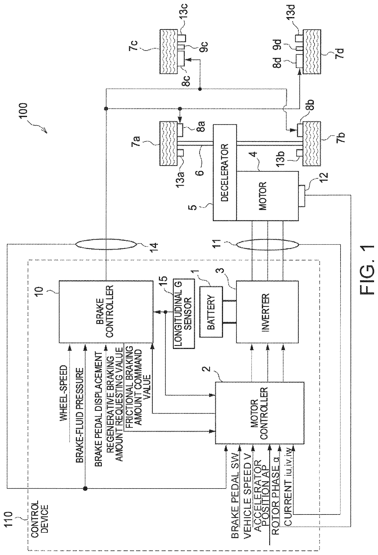
[0037]FIG. 1 is a block diagram showing the major configuration of an electric vehicle 100 including a control device according to a first embodiment of the present invention.

[0038]The electric vehicle 100 includes an electric motor as a driving source. The electric vehicle 100 of the first embodiment allows a driver to control the acceleration or deceleration and the stop of the electric vehicle 100 by adjusting the depression amount of an accelerator pedal. To accelerate the electric vehicle 100, the driver depresses the accelerator pedal down. To decelerate or stop the electric vehicle 100, the driver reduces the depression amount of the accelerator pedal or adjusts the depression amount of the accelerator pedal to zero.

[0039]The electric vehicle 100 includes a motor 4, a decelerator 5, a drive shaft 6, driving wheels 7a and 7b, driven wheels 7c and 7d, friction brakes 8a and 8d, parking brakes 9c and 9d, a current sensor 11, a rotation sensor 12, a wheel-speed sensor 13a to 13d,...

second embodiment

[0248]FIG. 13 is a block diagram showing one example of the configuration of the gradient torque calculation unit 22 in the second embodiment of the present invention.

[0249]The gradient torque calculation unit 22 of the second embodiment corrects a gradient torque estimated value Td* from the control block 225 shown in FIG. 6 so as not to provide uncomfortable feeling to the driver of the electric vehicle 100 travelling on an uphill road or a downhill road. This gradient torque calculation unit 22 includes, in addition to the configuration (including 221 to 225) in FIG. 6, a parking brake detection unit 226, a first gain setting unit 227, a second gain calculation unit 228, a max select 229, and a gradient torque correction unit 230.

[0250]The parking brake detection unit 226 detects the operating state of the parking brakes 9c and 9d. The parking brake detection unit 226 outputs a detection signal PB indicating the detected state of the parking brakes 9c and 9d to the first gain set...

third embodiment

[0273]FIG. 15 is a block diagram showing one example of the configuration of the gradient torque calculation unit 22 in the third embodiment of the present invention.

[0274]When it is determined that the electric vehicle 100 is in a slipping state, the gradient torque calculation unit 22 of the third embodiment limits the gradient torque estimated value Td*. This gradient torque calculation unit 22 includes, in addition to the configuration (including 226 to 230) in FIG. 13, a driving-wheel speed calculation unit 231, a driven-wheel speed calculation unit 232, a slip determination unit 233, a mask setting unit 234, and a gradient torque limiting unit 235.

[0275]The driving-wheel speed calculation unit 231 calculates the speed for the driving wheels 7a and 7b based on the detection values of the wheel-speed sensors 13a and 13b. The driving-wheel speed calculation unit 231 of the third embodiment calculates an average speed WS1ave of the driving wheels 7a and 7b based on the detection v...


PUM


Abstract

A method for controlling a vehicle that includes a motor configured to provide a driving/braking force to the vehicle and a friction braking mechanism configured to provide a friction brake force to the vehicle includes a target calculation step of calculating a target torque of the motor in accordance with a displacement of an accelerator pedal, a gradient estimation step of estimating a gradient torque to cancel a disturbance due to a gradient of a road surface where the vehicle is travelling, a command calculation step of calculating a torque command value of the motor based on the gradient torque and the target torque, a control step of controlling a torque of the motor in accordance with the torque command value, and a stop control step.

Description

[0001]The present application claims priority to Japanese Patent Application No. 2017-010565 filed with the Japan Patent Office on Jan. 24, 2017, the contents of which are hereby incorporated by reference in their entirety.BACKGROUNDTechnical Field[0002]The present invention relates to a control device for vehicle configured to control a driving / braking force and a friction braking force of the motor to stop the vehicle and relates to such a control method.Related Art[0003]Conventionally techniques for the acceleration / deceleration control system of a vehicle have been known, which control the deceleration in accordance with the accelerator displacement when the accelerator displacement is less than a predetermined value and control the acceleration in accordance with the accelerator displacement when the accelerator displacement is the predetermined value or more (see JP2000-205015A). Such an acceleration / deceleration control system sets a target acceleration / deceleration in accord...

Claims


Application Information

Patent Timeline
IPC IPC(8): B60L15/20B60L50/51
CPCB60L15/2018B60L15/20B60L2240/36B60L2240/423B60L50/51B60L2210/40B60T7/12B60W10/08B60W10/188B60W40/076B60W30/181B60W30/18118B60W2540/10B60W2520/10B60W2710/182B60W2710/083B60W2510/184B60W10/182B60W2520/26B60W30/18127B60W2510/081B60W2050/0056B60W2552/15B60L15/2009B60L15/2072B60L15/2081B60L2250/26B60L2240/463B60L2240/642B60L7/26B60L7/18Y02T90/16Y02T10/70B60L7/24B60W40/105B60L2250/28B60L2260/22B60L2240/12B60W2520/04B60W2510/083B60Y2300/18091B60Y2200/91B60W30/18B60W50/00
Inventor SHINDO, IKUMASUZUKI, TATSUYAOHTA, MITSUNORI
Owner NISSAN MOTOR CO LTD
Why Eureka
Try Eureka