Infrared sensor chip, and infrared sensor employing same

Active Publication Date: 2019-12-19
PANASONIC INTELLECTUAL PROPERTY MANAGEMENT CO LTD
View PDF0 Cites 1 Cited by
  • Summary
  • Abstract
  • Description
  • Claims
  • Application Information

AI Technical Summary

Benefits of technology

The present invention aims to solve the problem of inaccuracy in self-diagnostics in infrared sensors. The aim is to provide an infrared sensor that is designed to accurately perform self-diagnosis.

Problems solved by technology

In Patent Literature 1, however, even when breakage occurs or starts to occur in part of a bridge of the infrared detection element, the breakage cannot be accurately detected if an output of the infrared detection element does not decrease.
Therefore, Patent Literature 1 has a problem that a sufficient self-diagnostic function cannot be obtained.

Method used


Image

  • Infrared sensor chip, and infrared sensor employing same
  • Infrared sensor chip, and infrared sensor employing same
  • Infrared sensor chip, and infrared sensor employing same

Examples


first embodiment

[0032]An infrared sensor chip and an infrared sensor in a first embodiment will be described below with reference to the drawings.

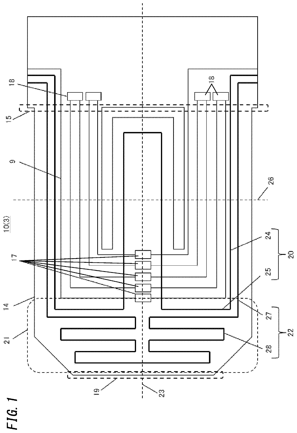
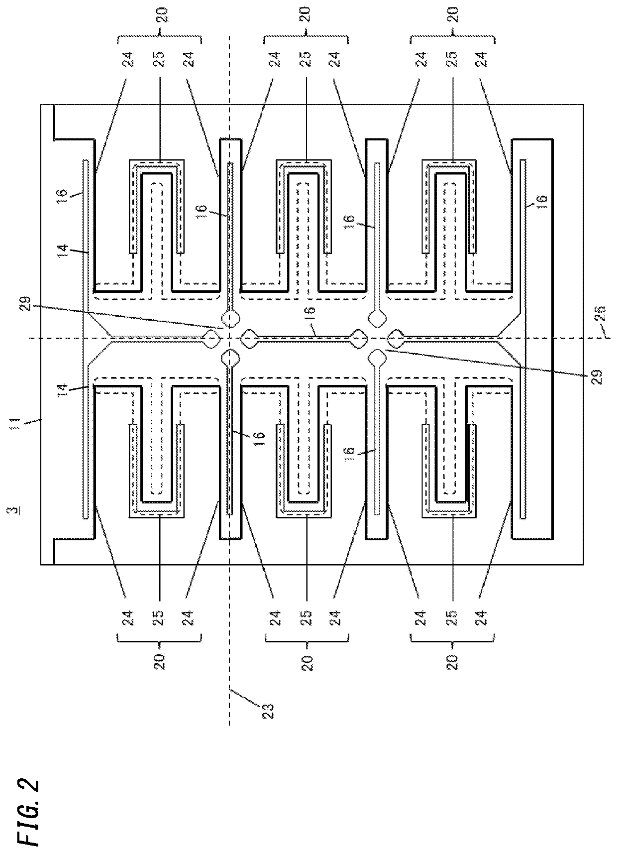
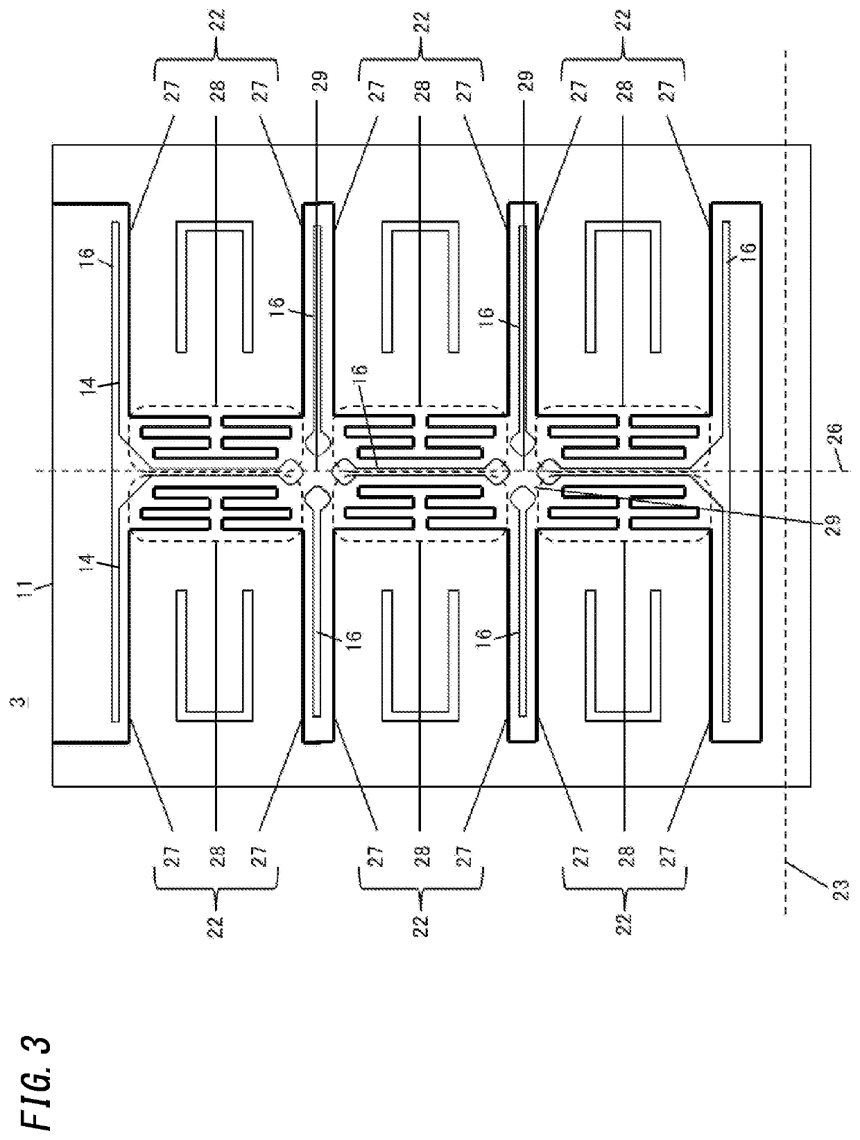
[0033]FIG. 1 is an enlarged view illustrating a bridge section of an infrared sensor chip of the first embodiment. FIGS. 2 and 3 are enlarged views each illustrating a pixel section of the infrared sensor chip. FIG. 4 is a side sectional view illustrating the pixel section of the infrared sensor chip. FIG. 5 is a side sectional view illustrating an infrared sensor including the infrared sensor chip. FIG. 6 is a top view illustrating an arrangement of pixel sections of the infrared sensor chip. FIG. 7 is an equivalent circuit diagram illustrating breakage detection wirings of the infrared sensor. FIG. 8 is an equivalent circuit diagram illustrating heater wirings of the infrared sensor.

[0034]As illustrated in FIG. 5, an infrared sensor 1 includes a base 2, an infrared sensor chip 3 provided on the base 2, a process circuit 4 configured to process an output...

second embodiment

[0049]An infrared sensor chip of a second embodiment will be described with reference to the drawings.

[0050]FIG. 11 shows wiring of heater wirings 32 of an infrared sensor chip 31 in a pixel section 11 according to the second embodiment.

[0051]The infrared sensor chip 31 of the second embodiment includes a plurality of pixel sections 11 arranged in an array. Each pixel section 11 has a supporting substrate 13 having a cavity 12, a thin film structure section 10 supported by the supporting substrate 13, and bridge sections 14 included in the thin film structure section 10. In each bridge sections 14, a thermopile wiring 9, a breakage detection wiring 20, and a heater wiring 32 are provided, so that self-diagnosis of the infrared sensor 1 is possible. Note that although not shown in FIG. 11, the breakage detection wiring 20 is wired to be in the same shape as that in the infrared sensor chip 3 in the first embodiment.

[0052]In the infrared sensor chip 31 of the second embodiment, the he...

third embodiment

[0054]An infrared sensor chip including a diode in the vicinity of the infrared sensor chip has been known (WO 2002 / 075262).

[0055]Moreover, an infrared sensor including a substrate, an infrared sensor chip disposed on the substrate, and a package covering the infrared sensor chip has been known (WO 2011 / 162346).

[0056]In the infrared sensor chip disclosed in Patent Literature 1, however, diodes enclose the entire periphery of the infrared sensor chip, and therefore, the size of the infrared sensor increases. The infrared sensor disclosed in Patent Literature 2 includes a thermistor, and therefore, the size of the infrared sensor increases.

[0057]It is an object of the present disclosure to provide an infrared sensor which solves the problems and which is configured to measure a temperature of the infrared sensor chip without increasing the size of the infrared sensor.

[0058]An infrared sensor chip and an infrared sensor in a third embodiment will be described below with reference to th...


PUM


Abstract

The disclosure has a configuration including: a supporting substrate having a cavity; at least one bridge section extending directly above the cavity and having at least one end supported by the supporting substrate and an other end; and a thermopile wiring formed in the bridge section and including hot junctions in the bridge section and cold junctions directly above the supporting substrate, the hot junctions being connected to the cold junctions. The bridge section is provided with: at least one breakage detection wiring for detecting breakage of the bridge section; and at least one heater wiring. The breakage detection wiring is wired along the thermopile wiring. The heater wiring is wired such that part of the heater wiring is in an area between the other end of the bridge section and the hot junctions.

Description

TECHNICAL FIELD[0001]The present disclosure relates to an infrared sensor chip configured to detect a temperature of an object in a non-contact manner and an infrared sensor employing the infrared sensor chip.BACKGROUND ART[0002]An infrared sensor has been known which includes an infrared detection element provided with a heater wiring to be able to detect breakage of a wire (Patent Literature 1).[0003]In Patent Literature 1, however, even when breakage occurs or starts to occur in part of a bridge of the infrared detection element, the breakage cannot be accurately detected if an output of the infrared detection element does not decrease. Therefore, Patent Literature 1 has a problem that a sufficient self-diagnostic function cannot be obtained.CITATION LISTPatent Literature[0004]Patent Literature 1: JP 2011-27652 ASUMMARY OF INVENTION[0005]It is an object of the present disclosure to provide an infrared sensor which solves the problem and which is configured to accurately perform s...

Claims


Application Information

Patent Timeline
IPC IPC(8): G01J5/16G01J5/20G01J5/04
CPCG01J5/20G01J5/045G01J5/16H01L27/144H01L27/146G01J5/12G01J5/026G01J5/024
Inventor KAKIMOTO, KATSUMIOKUDO, TAKAFUMIHAGIHARA, YOSUKEMATSUURA, AKIRA
Owner PANASONIC INTELLECTUAL PROPERTY MANAGEMENT CO LTD
Why Eureka
Try Eureka