Structure for reducing the drag of a ship and its application

a technology for reducing the drag of ships and ships, applied in the direction of watercraft hull design, hull construction, etc., can solve the problems of increasing fuel consumption, slowing down the speed of ships, and ship drag, so as to and reduce the drag of ships

Inactive Publication Date: 2019-12-26
MEI CHEN HSIN
View PDF9 Cites 0 Cited by
  • Summary
  • Abstract
  • Description
  • Claims
  • Application Information

AI Technical Summary

Benefits of technology

[0006]In view of achieving the aforementioned purpose, the present invention provides a structure installed on the hull of a ship and its application for reducing the drag of a ship, which include at least one or a plurality of turbulence generating structures installed on the surface of the hull of the ship to generate a beneficial turbulence that reduces the thickness of the boundary layer on the surface of the hull and thereby delays the separation and increases the pressure of the aft part of the hull to speed up the ship.
[0017]The structure for reducing the drag of a ship and its application according to the present invention comprises a hull and at least one turbulence generating structure. The turbulence generating structure is installed on the side surface between the widest section and aft end of the hull, or on the bottom surface between the deepest portion and the aft end of the ship to generate turbulence, and thereby reduce the drag of the ship.
[0018]By installing at least one turbulence generating structure on the surface between the widest section and the aft end or the deepest portion and the aft end of the hull, the at least one turbulence generating structure of the present invention may generate a beneficial turbulence behind the turbulence generating structure to thin the boundary layer, which in turn may delay the separation to reduce the drag of the ship and effectively increase the speed of the ship. Consequently, both fuel consumption and navigation time can be effectively saved.

Problems solved by technology

A ship suffers drag while sailing, which slows down the speed of ship.
The drag causes not only more fuel consumption, but also wears down the motor and the transmitting mechanism, as well as producing more exhaust gas and increasing the time to complete the voyage.
The environmental pollution, extra fuel consumption and time loss to the transportation field are inevitable.
Although the streamlining of the shape of ship's hull is helpful to reduce drag, the effect is still limited.
The difference in the longitudinal pressure also causes drag on the ship.
Accordingly, the aforesaid various kinds of drag are detrimental to the ship's speed.

Method used


Image

  • Structure for reducing the drag of a ship and its application
  • Structure for reducing the drag of a ship and its application
  • Structure for reducing the drag of a ship and its application

Examples


Embodiment Construction

[0035]In order to lay out the above and other purposes, features and advantages of the present invention more explicitly, the embodiments are described herein with reference to the accompanying drawings.

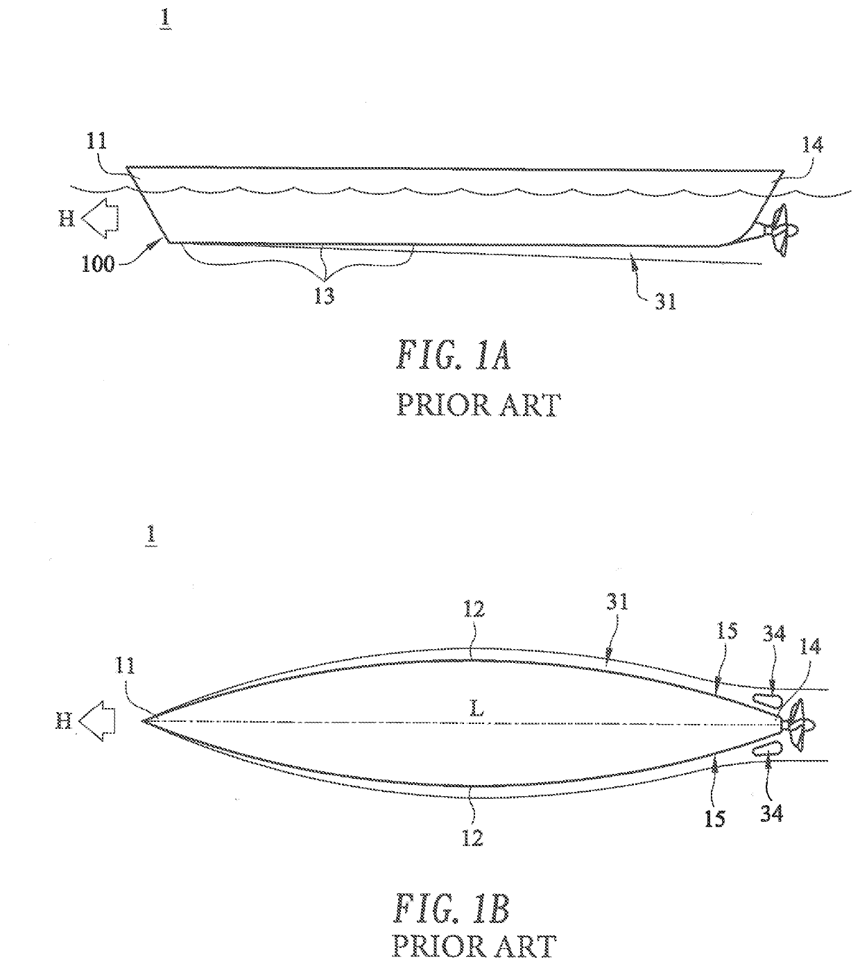
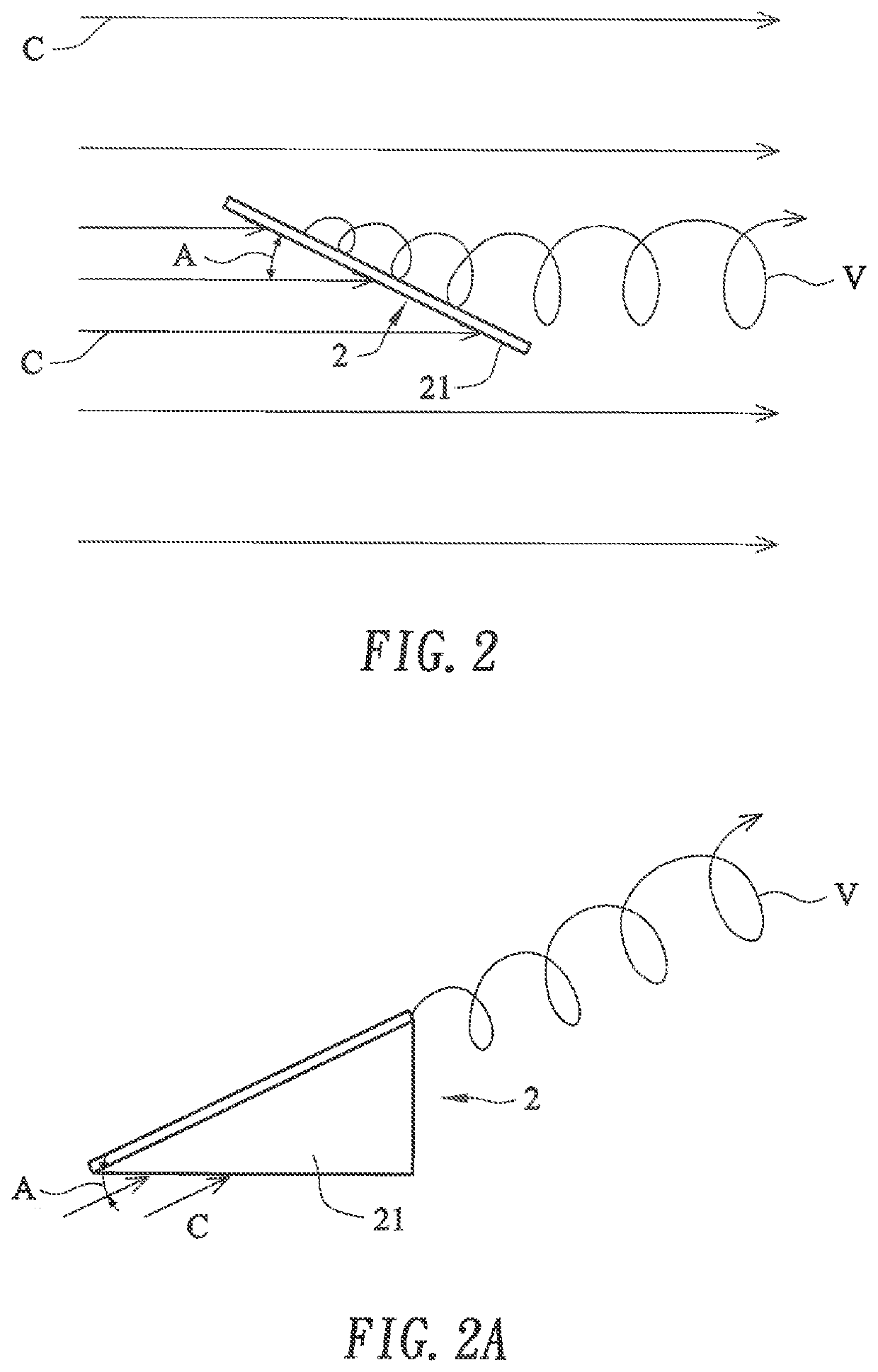
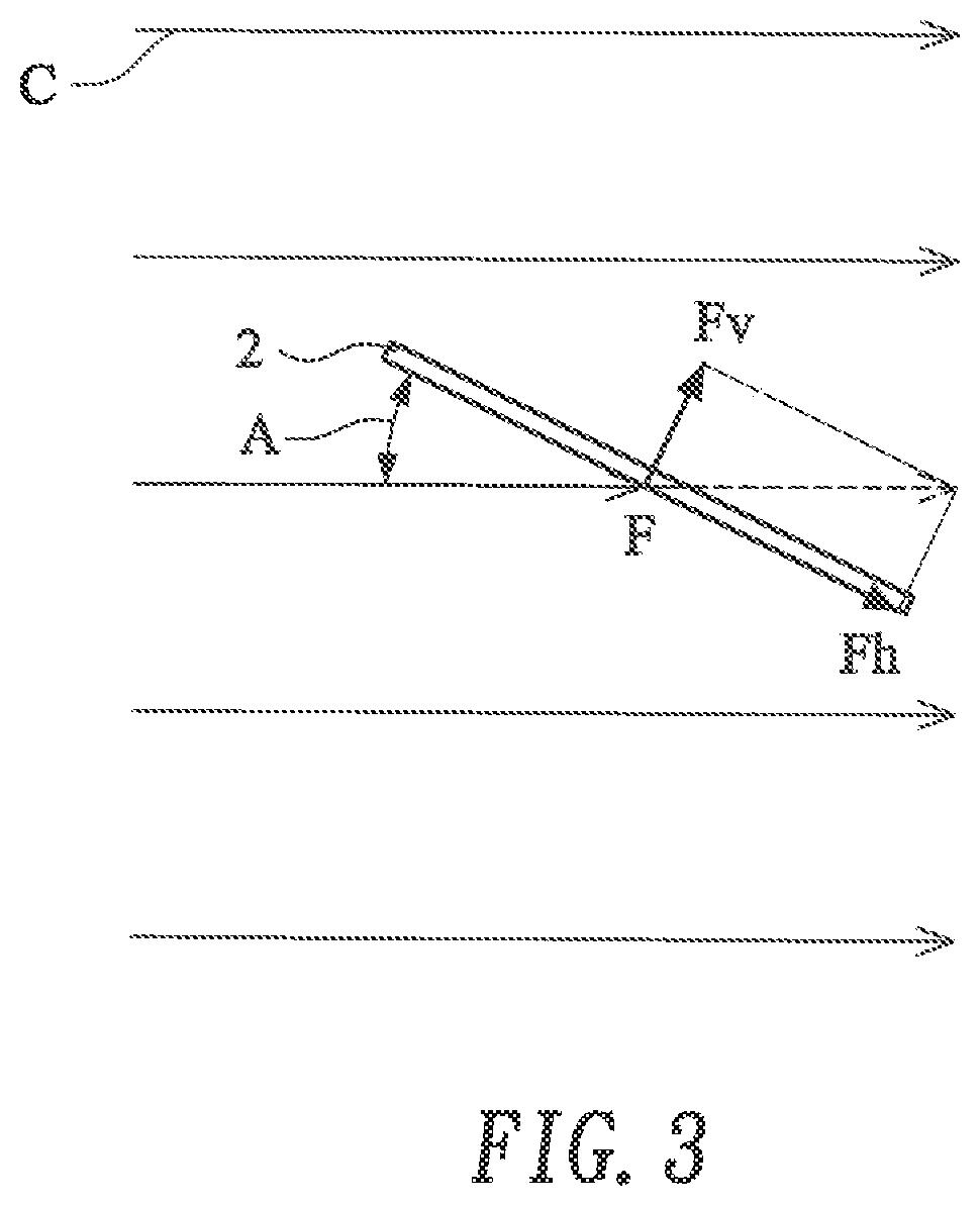
[0036]Referring to FIGS. 2 and 3, the variation and the effects of the current when it encounters the turbulence generating structure of the present invention is described as follows. As shown in FIG. 2 and FIG. 7, a turbulence generating structure 2 installed on the hull 100 of a ship 1 comprises an impact surface 21 facing the incoming flow of water for colliding with and generating turbulence when the flow collides with the impact surface 21. The turbulence generating structure 2 also comprises a front surface 22 with a shape of a slope or curved surface as shown in FIG. 12. When the ship 1 is in the H sailing traveling forward, the front surface 22 of the turbulence generating structure 2 face water current. Since the shape of the front surface 22 is a slope or curved surface, th...


PUM


Abstract

A structure for reducing the drag of a ship and its application thereof is provided. The structure for reducing the drag of a ship includes at least one turbulence generating structure which is installed on the side surface between the widest section and the aft end or on the bottom surface between the deepest portion and the aft end of the ship. The arrangement of the turbulence generating structure can generate turbulence to reduce the drag of the ship, and thereby increase the speed of the ship and / or reduce the ship's fuel consumption.

Description

FIELD OF THE INVENTION[0001]The present invention relates to the structure of a ship and its application thereof for reducing drag of the ship while sailing, and particularly to a ship having a turbulence generating structure on the surface of the hull for generating turbulence to reduce drag of the ship and its application thereof.DESCRIPTION OF RELATED ART[0002]A ship suffers drag while sailing, which slows down the speed of ship. The drag causes not only more fuel consumption, but also wears down the motor and the transmitting mechanism, as well as producing more exhaust gas and increasing the time to complete the voyage. The environmental pollution, extra fuel consumption and time loss to the transportation field are inevitable.[0003]Although the streamlining of the shape of ship's hull is helpful to reduce drag, the effect is still limited. Referring to FIGS. 1A and 1B, a perspective view of a conventional ship sailing in the water is shown. The ship 1 comprises a hull 100. The...

Claims


Application Information

Patent Timeline
Patent Type & Authority Applications(United States)
IPC IPC(8): B63B1/34
CPCB63B2241/10B63B2231/02B63B2231/40B63B1/34B63B1/36Y02T70/10
Inventor MEI, CHEN-HSIN
Owner MEI CHEN HSIN
Why Eureka
Try Eureka