Alternative method of heat removal from an internal combustion engine

a technology of internal combustion engine and heat removal, which is applied in the direction of machines/engines, transportation and packaging, and jet propulsion mounting, etc., can solve the problems of reducing fuel efficiency on virtually every car, and achieve the effects of improving vehicle performance and fuel efficiency, and great aerodynamic efficiency

Active Publication Date: 2021-05-18
MOORE JAMES
View PDF33 Cites 0 Cited by
  • Summary
  • Abstract
  • Description
  • Claims
  • Application Information

AI Technical Summary

Benefits of technology

[0007]The condensation cooling system of the present invention improves upon the prior art by providing a cooling system that replaces the radiator of conventional automobile cooling systems with a liquid-to-liquid heat exchanger immersed in a coolant tank having a condensing surface exposed to airflow. The system allows the heat exchanger to be relocated from the front of a vehicle to the rear or side of a vehicle. Such alternative placement, allows for the front of a vehicle to be designed for greater aerodynamic efficiency which, given the reduction in vehicle drag, allows for improvements in vehicle performance and, in particular, fuel efficiency.
[0012]Generally, for the condensation cooling system of the present invention to operate effectively, the boiling point of the second coolant should be lower than that of the first coolant. The airflow of the second coolant vapor inside the coolant tank and hence the ability of the system to remove heat, may be increased with the use of one or more in-tank mounted electric, axial fans which are positioned so as to blow across the surface of the second coolant. The flow of the hot second coolant vapor in the tank may be managed to move the vapor efficiently to the condensing panel, minimizing obstructions, eddies, and stagnant zones. In-tank mounted diffuser plates may be desirable to create and enhance desirable vapor flow conditions.
[0014]Turbulent airflow over an exterior surface of the condensing panel is expected to provide increased convection cooling of the second coolant vapor over that of laminar airflow by reducing the boundary layer thickness of the air at the exterior surface of the condensing panel. To manage the airstream and increase turbulence, and thus cooling capacity, aerodynamic features such as canted fins may be mounted on the outside surface of the condensing panel. Fins and like aerodynamic features also serve to suppress flow separation over the condensing panel. Suppression of flow separation aids in reducing drag over the condensing panel.

Problems solved by technology

Although conventional pressurized, liquid coolant systems have proven reliable in automotive vehicle applications, they have several inherent drawbacks.
This results in drag which necessarily reduces fuel efficiency on virtually every car with an internal combustion engine.

Method used


Image

  • Alternative method of heat removal from an internal combustion engine
  • Alternative method of heat removal from an internal combustion engine
  • Alternative method of heat removal from an internal combustion engine

Examples


Embodiment Construction

[0028]The present invention will now be described more fully hereinafter with reference to the accompanying drawings, in which preferred embodiments of the invention are shown. The invention may, however, may be embodied in many different forms and should not be construed as being limited to the embodiments set forth herein. Rather these embodiments are provided so that this disclosure will be thorough and complete, and will fully convey the scope of the invention to those skilled in the art. Like numbers refer to like elements throughout.

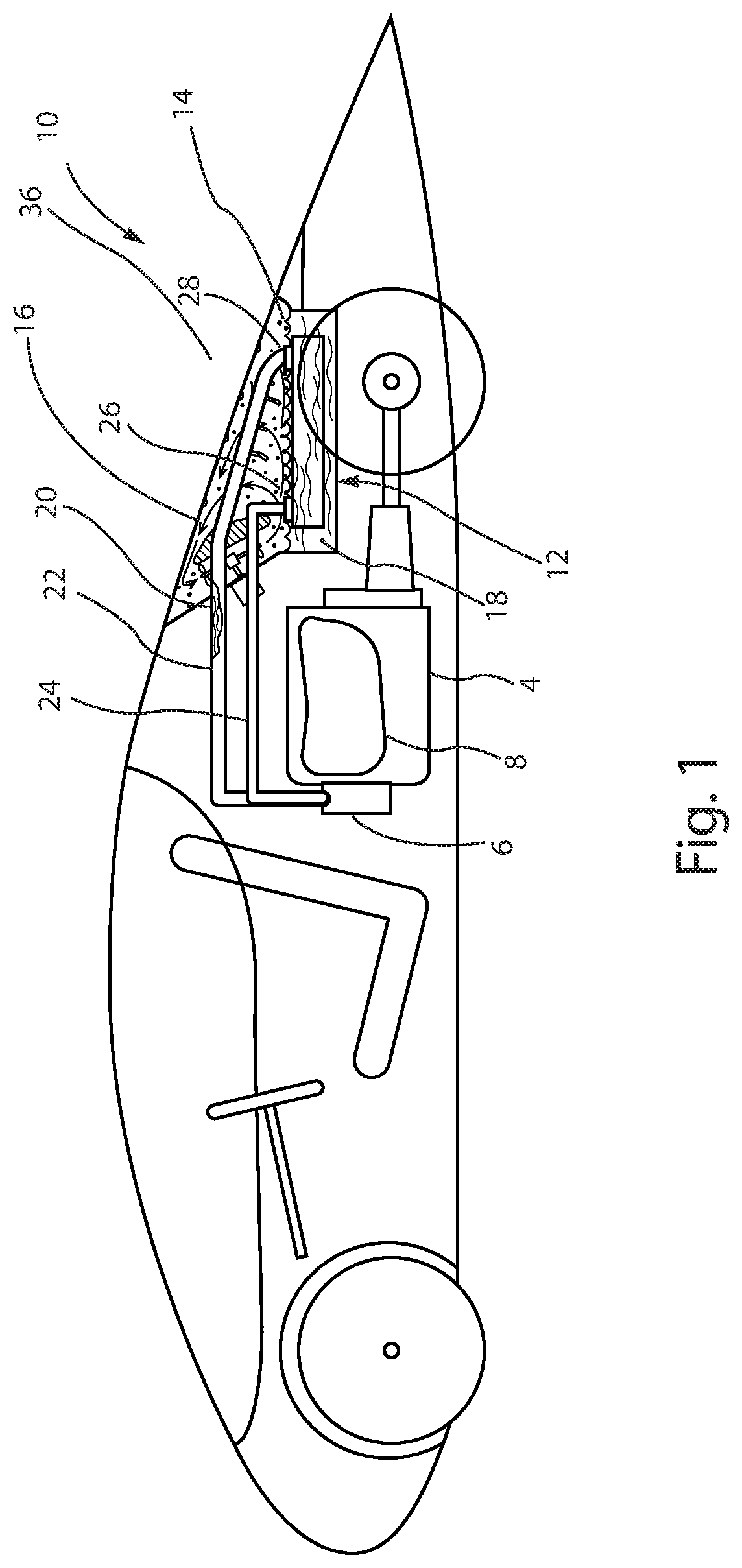
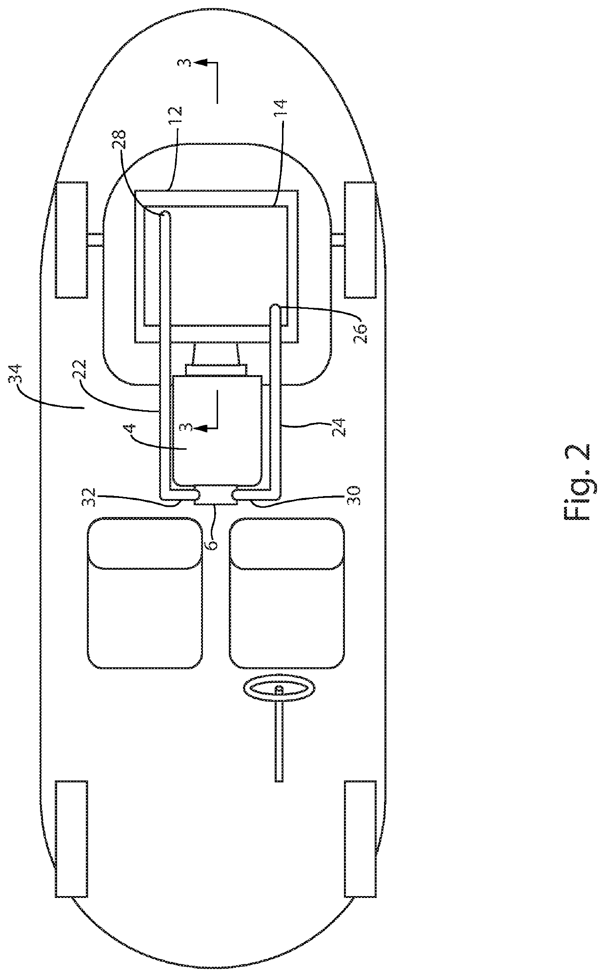
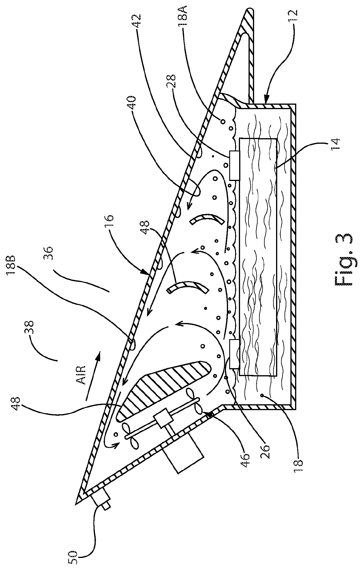
[0029]With reference to FIGS. 1-2, a motor vehicle 2 having an internal combustion engine 4 which includes a coolant jacket 8 and a coolant pump 6 is shown. Enclosed within the motor vehicle 2 is a condensation cooling system 10 in accordance with the present invention. The condensation cooling system 10 comprises a liquid-to-liquid heat exchanger 14 for circulating a first coolant 20, a coolant tank 12 for circulating a second coolant 18, and a co...


PUM


Abstract

A condensation cooling system for motor vehicles is presented. The system, in principal part, comprises a liquid-to-liquid heat exchanger for circulating a first coolant, a coolant tank for circulating a second coolant, and a condensing panel or surface, where the condensing panel is part of the coolant tank and also functions as a vehicle body panel. These components are arranged in two circuits, i.e. an engine cooling circuit in which a first coolant is circulated and a vapor condensing circuit in which a second coolant is circulated. The two cooling circuits are interconnected by the coolant tank where the heat exchanger is positioned within the coolant tank such that it is immersed in the second coolant. The coolant tank may also be equipped with pressure release valves, electric fans and diffuser plates to control pressure and manage air and vapor flow internally within the tank.

Description

CROSS-REFERENCES TO RELATED APPLICATION[0001]This application claims the benefit of U.S. Provisional Application Ser. No. 62 / 832,184, filed Apr. 10, 2019 and entitled “Alternative Method of Heat Removal from an Internal Combustion Engine,” which is incorporated herein by this reference.BACKGROUND OF THE INVENTIONField of the Invention[0002]The present invention relates generally to cooling systems for internal combustion engines and more particularly to a condensation cooling system for use in a motor vehicle.Background of the Invention[0003]Removal of heat from an internal combustion engine is necessary for the proper function and survival of the engine. Conventional automotive cooling systems are pressurized, forced circulation, cooling systems in which water or a water-antifreeze mixture is circulated by an engine-driven or electrically driven pump in a single closed loop circuit. The cooling circuit comprises the engine water jacket, where heat from the engine's cylinders and cy...

Claims


Application Information

Patent Timeline
Patent Type & Authority Patents(United States)
IPC IPC(8): F01P3/18F01P5/10F01P11/10B60K11/02F01P3/02F01P3/22B60K11/06F01P3/00
CPCF01P5/10B60K11/02B60K11/06F01P3/02F01P3/2285F01P11/10F01P2003/001F01P2003/2214B60K11/04B60K2005/003F01P3/2271F01P9/02F01P11/029F01P11/0295
Inventor MOORE, JAMES
Owner MOORE JAMES
Why Eureka
Try Eureka