
Locating device

Active Publication Date: 2019-12-26
HANWIT PRECISION IND LTD
View PDF0 Cites 1 Cited by
  • Summary
  • Abstract
  • Description
  • Claims
  • Application Information

AI Technical Summary

Benefits of technology

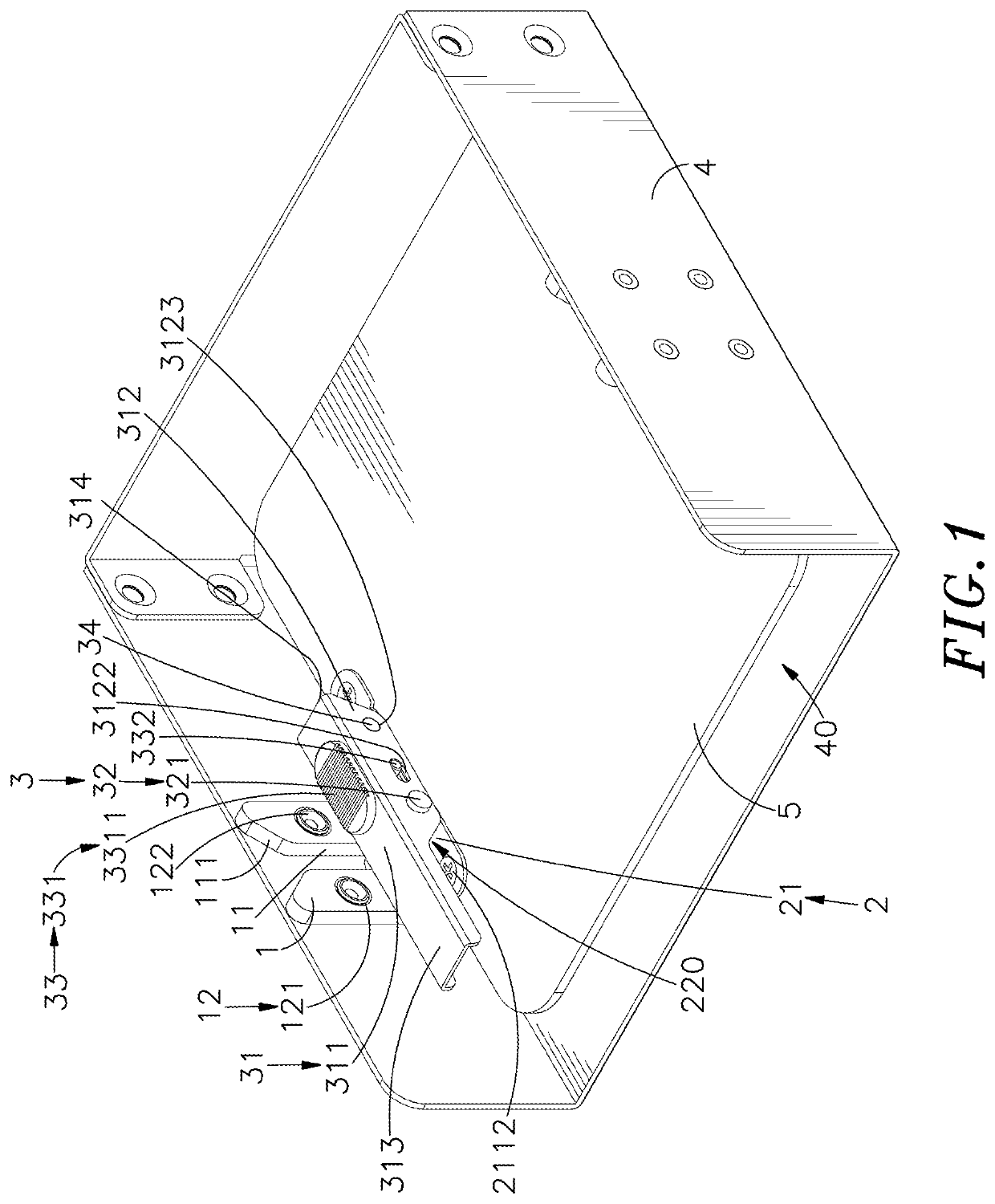
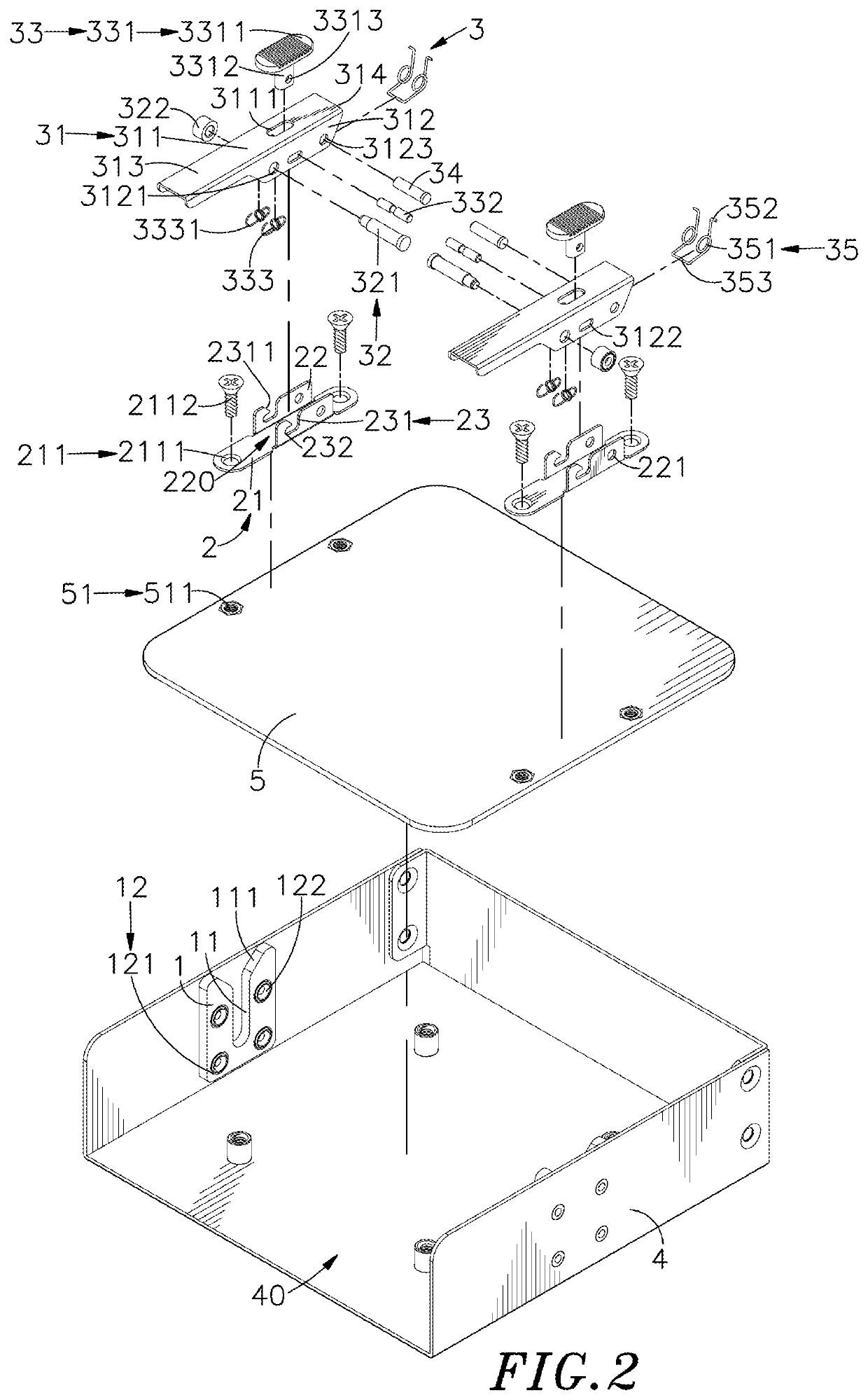
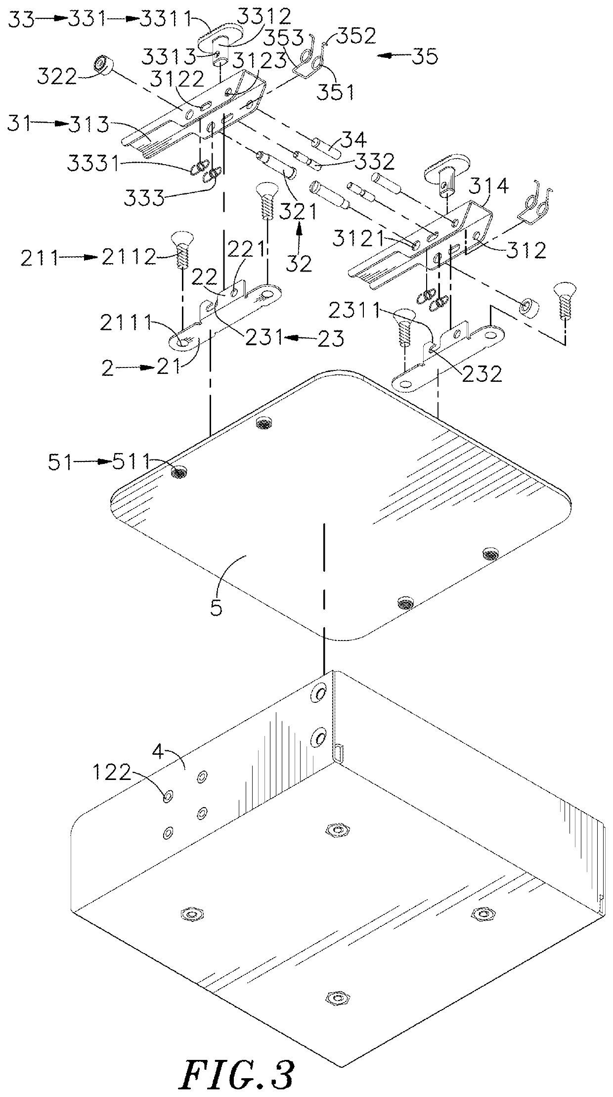
The present invention provides a locating device with a guiding member and a sliding member. The guiding member has a guiding channel inwardly cut through a top, and the sliding member has side plates bent from two opposite sides in the same direction, each side plate has a locating part disposed thereon. A pulling assembly is provided with a pulling body pivotally connected to the sliding member, and the pulling body has a guiding element and a fastening element disposed on a side opposite to the guiding element. The pulling body can be pulled to rotate, and the guiding element can be guided and slid in the guiding channel of the guiding member, simultaneously moving the sliding member in another direction opposite to the sliding direction of the guiding element. After the pulling body is pulled and rotated, the fastening element of the pulling assembly can be located on the locating part of the sliding member to lock the pulling assembly, reducing operational difficulty and improving assembly speed. The pulling body can use the supporting surface to abut against the surface of the base of the sliding member, preventing excessive pulling and shaking during the assembly process, improving accuracy and stability of the assembly process.

Problems solved by technology

The screw locking manner requires a lot of screws, and the screws also must be removed one by one in order to demount the storage medium machine, and it results in a lot of man-hours for assembly, and significantly increased downtime for maintenance.
When the chassis is filled with interface cards, storage medium machines, power lines, cables and other devices, it is very inconvenient to insert a tool for locking screw, and the screw possibly falls to lost during the locking operation.
Furthermore, if the size of the screw does not match the screw hole but the screw is still locked into the screw hole by force, it is easy to damage the screw hole on the storage medium machine, and it is not convenient for further assembly or disassembly.

Method used


Image

  • Locating device
  • Locating device
  • Locating device

Examples


Embodiment Construction

[0020]The following embodiments of the present invention are herein described in detail with reference to the accompanying drawings. These drawings show specific examples of the embodiments of the present invention. It is to be understood that these embodiments are exemplary implementations and are not to be construed as limiting the scope of the present invention in any way. Further modifications to the disclosed embodiments, as well as other embodiments, are also included within the scope of the appended claims. These embodiments are provided so that this disclosure is thorough and complete, and fully conveys the inventive concept to those skilled in the art. Regarding the drawings, the relative proportions and ratios of elements in the drawings may be exaggerated or diminished in size for the sake of clarity and convenience. Such arbitrary proportions are only illustrative and not limiting in any way. The same reference numbers are used in the drawings and description to refer to...


PUM


Abstract

A locating device includes a guiding member, a sliding member and a pulling assembly. The guiding member includes a guiding channel inwardly cut through a top thereof, and the sliding member has side plates which each has a locating part. The pulling assembly comprises a pulling body having a guiding element, a fastening element disposed on a side thereof opposite to the guiding element. When the pulling body is in an open state, the fastening element is not located on the locating part; when the pulling body performs a locking operation, the guiding element is slid in the guiding channel and the sliding member is simultaneously slid in another direction opposite to the guiding element; when the pulling body is in a locked state, the fastening element is located on the locating part. Therefore, operational difficulty can be reduced and assembly speed can be improved.

Description

[0001]This application claims the priority benefit of Taiwan patent application number 107121932, filed on Jun. 26, 2018.BACKGROUND OF THE INVENTION1. Field of the Invention[0002]The present invention provides a locating device, more particularly to the locating device including a pulling assembly, and when the pulling assembly is pulled to rotate, a guiding element can be slid in a guiding channel of a guiding member, so as to simultaneously move the sliding member towards another direction opposite to the sliding direction of the guiding element, and after the pulling assembly is pulled and rotated, a fastening element of the pulling assembly can be located on a locating part of the sliding member to form a locked state, thereby reducing operational difficulty and improving assembly speed.2. Description of the Related Art[0003]With developments of network cloud technology and Internet of Things technology, the requirements for the computer servers and industrial computer servers a...

Claims


Application Information

Patent Timeline
IPC IPC(8): H05K7/14H05K7/18H05K5/02
CPCH05K5/0221H05K7/1489H05K7/18G11B33/123
Inventor WU, MING-DECHANG, CHING-KAI
Owner HANWIT PRECISION IND LTD
Features
  • Generate Ideas
  • Intellectual Property
  • Life Sciences
  • Materials
  • Tech Scout
  • Unparalleled Data Quality
  • Higher Quality Content
  • 60% Fewer Hallucinations
Learn More