Eureka AIR delivers breakthrough ideas for toughest innovation challenges, trusted by R&D personnel around the world.

Light assembly

Active Publication Date: 2020-01-16
TANG YI WEN
View PDF10 Cites 6 Cited by
  • Summary
  • Abstract
  • Description
  • Claims
  • Application Information

AI Technical Summary

Benefits of technology

The present invention is controlled by a remote controller that can turn on or off light members and adjust their brightness. This means that the control member does not need to be physically connected to the light members, making it easier to control and adjust the brightness from a distance.

Problems solved by technology

Such way of use is very inconvenient.

Method used


Image

  • Light assembly
  • Light assembly
  • Light assembly

Examples


Embodiment Construction

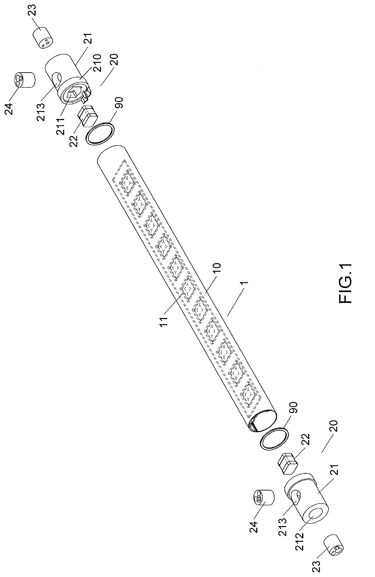
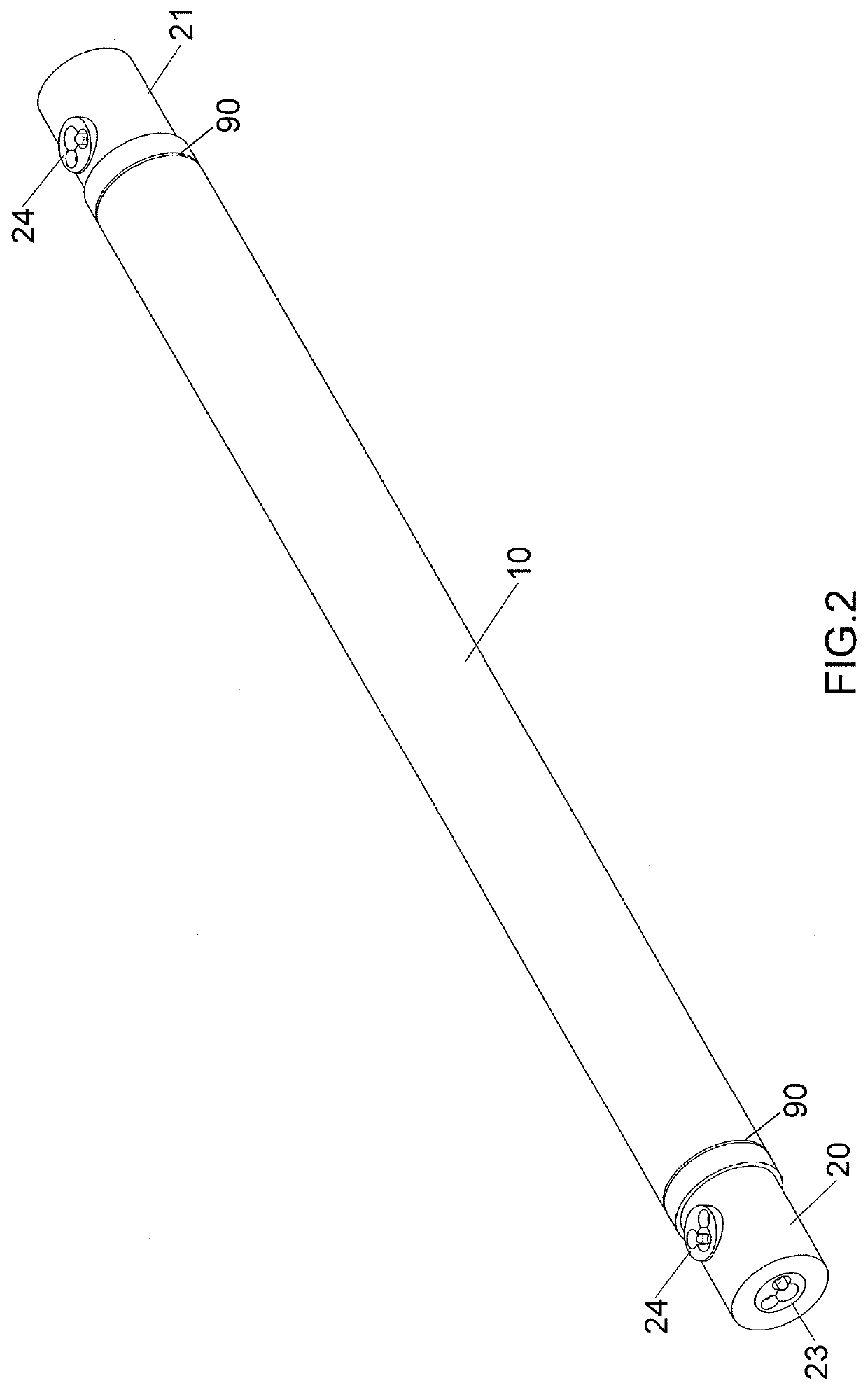
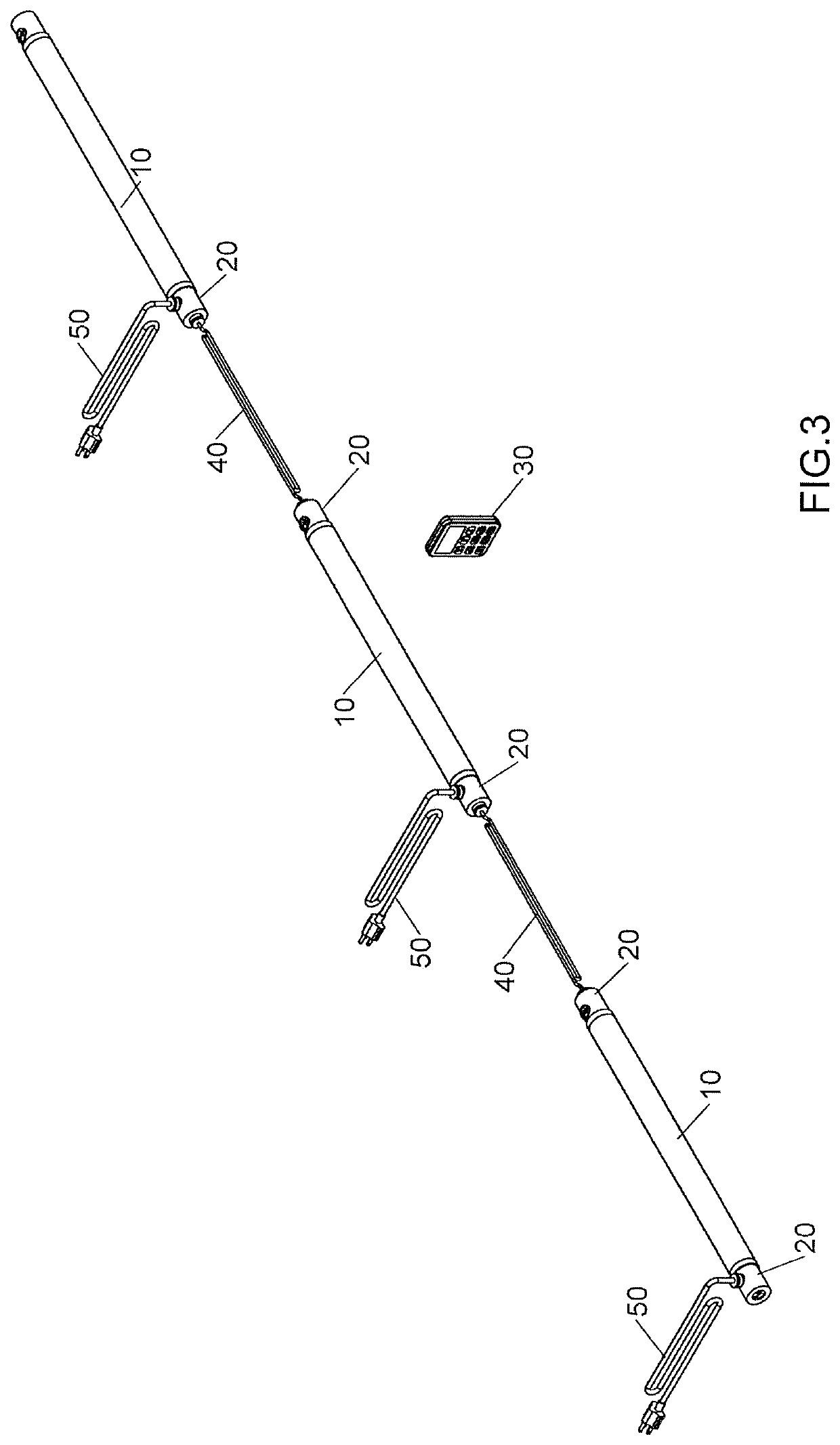
[0021]Referring to FIGS. 1 to 5, the light assembly of the present invention comprises multiple lighting sets 1. Each lighting set 1 comprises multiple first units 10 each having multiple light members 11 received therein. The first units 10 each is an elongate tubular unit, and a transparent or translucent unit. The light members 11 distribute in the first unit 10 along a straight line and equally spaced, so that the light members can emit light beams to evenly pass through the first unit 10.

[0022]Two second units 20 are respectively connected to two open ends of each of the first units 10 so as to seal the two open ends of the first unit 10. Each second unit 20 includes an end member 21, a control member 22, a first plug 23 and a second plug 24. The end member 21 is a cylindrical member and mounted to the open end of the first unit 10 corresponding thereto. At least one seal ring 90 is located between the end member 21 and each of the two open ends of the first unit 10 so as to be...


PUM


Abstract

A light assembly includes at least one lighting set and at least one remote controller. The lighting set comprises a first units, two end members, two first plugs, at least one control member and at least one second plug. The first unit has multiple light members received therein. The two end members, the two first plugs, the at least one control member and the at least one second plug are assembled together correspondingly. The at least one control member is signally and electrically connected with two first plugs and the at least one second plug. The first plugs of two lighting sets are connected with each other by a first connection cable. The second plug connects to a power source by a first power cable. The at least one remote controller is for emitting control signals to the at least one control member so as to control the light members.

Description

[0001]The present invention is a Continuation-In-Part application of applicant's former application with the application Ser. No. 15 / 862,622, filed on Jan. 4, 2018.BACKGROUND OF THE INVENTION1. Fields of the Invention2. Descriptions of Related Art[0002]The conventional light assembly is disclosed in FIG. 13, and comprises multiple light tubes 81 and each light tube 81 includes a fifth plug on each of two ends thereof. One sixth plug is located beside each fifth plug corresponding thereto. Multiple second power cables 82 are respectively connected to the sixth plugs of the multiple light tubes 81, and the multiple second power cables 82 are connected with a power source so as to provide electric power to activate the multiple light tubes 81. One second connection cable 83 is connected two respective fifth plugs of two light tubes 81 so that the light tubes 81 are activated simultaneously.[0003]It is noted that all of the light tubes 81 have to be connected to the second power cables ...

Claims


Application Information

Patent Timeline
IPC IPC(8): H05B37/02F21V15/015F21V3/02F21V23/00F21V31/00F21V23/06F21V21/005
CPCF21V21/005H01R33/06F21K9/27F21S4/20F21S2/005F21K9/272H05B47/19F21V15/015F21V3/02F21V31/005F21V23/003F21V23/06F21Y2103/10F21K9/275F21S4/28F21V23/001F21V23/045H01R31/02
Inventor TANG, YI-WEN
Owner TANG YI WEN
Why Eureka
Eureka Blog
Learn More