Cable handling system for longwall mining machines

a technology of mining machines and handling systems, which is applied in the direction of slitting machines, mechanical equipment, and cable arrangements between relatively moving parts, etc. it can solve the problems of large changes in the pan angle of the pan line, damage the bretby, and/or injure any personnel in the vicinity, so as to and facilitate the operation of the shearer

Active Publication Date: 2020-01-23
CATERPILLAR INC
View PDF0 Cites 7 Cited by
  • Summary
  • Abstract
  • Description
  • Claims
  • Application Information

AI Technical Summary

Benefits of technology

[0003]In one aspect, the disclosure is directed towards a cable handling system for a longwall mining machine. The longwall mining machine includes a shearer configured to move along a pan line to mine material along a mine face. The cable handling system includes a service line, multiple interconnected trays, and a controller. The service line is configured to carry one or more supply lines to the shearer for facilitating shearer operation. The interconnected trays accommodate the service line. Further, the controller is configured to determine a profile of the pan line, and detect one or more parameters associated with the service line in relation to the profile of the pan line. The controller is configured to determine a likelihood of at least a portion of the service line dislodging from the interconnected trays based on the one or more parameters exceeding a predefined threshold.
[0004]In another aspect, the disclosure relates to a longwall mining machine. The longwall mining machine includes a pan line, a shearer, a service line, multiple interconnected trays, and a controller. The shearer is configured to move along the pan line to mine material along a mine face. The service line is configured to carry one or more supply lines to the shearer for facilitating shearer operation. The interconnected trays accommodate the service line. The controller is ...

Problems solved by technology

Such a condition is further complicated by undulations in the mining seam (and/or environment) that can cause relatively large changes in the pan angles of the pan line.
Such unraveling of th...

Method used


Image

  • Cable handling system for longwall mining machines
  • Cable handling system for longwall mining machines
  • Cable handling system for longwall mining machines

Examples


Embodiment Construction

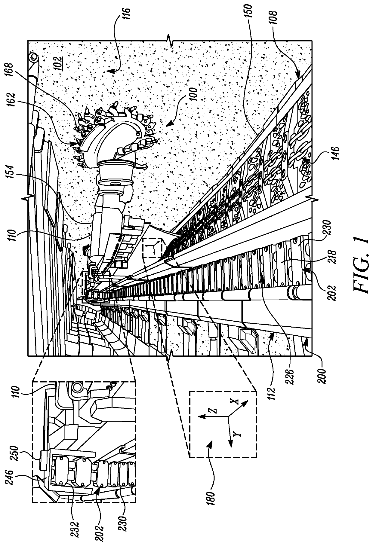
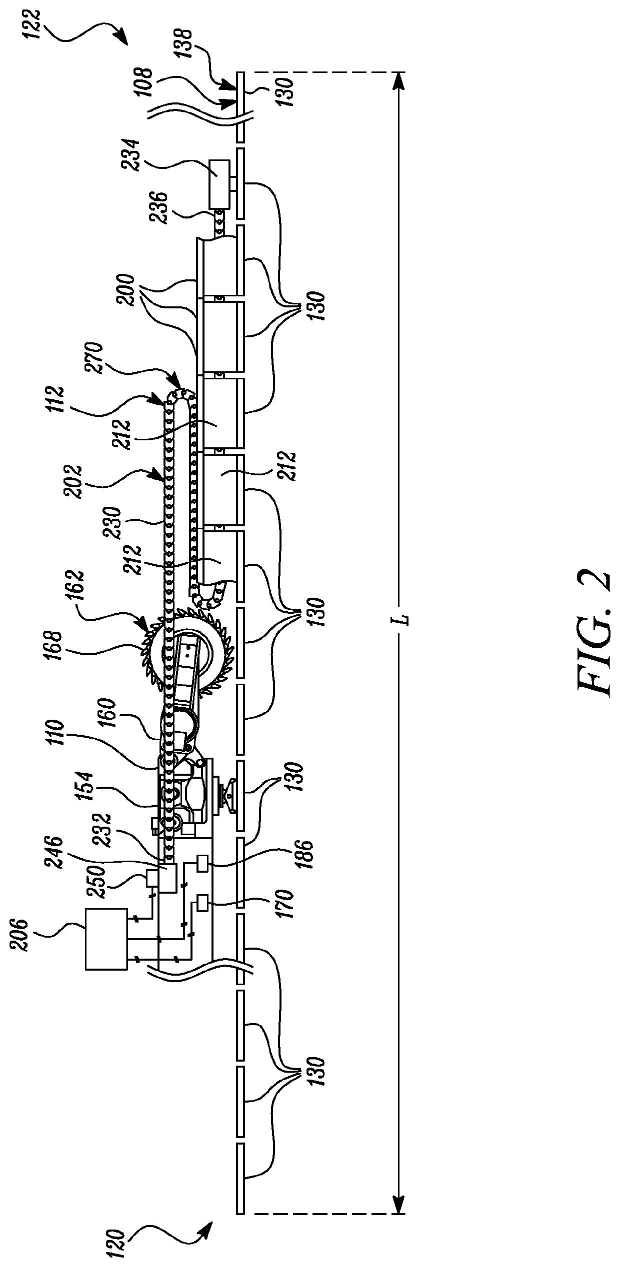
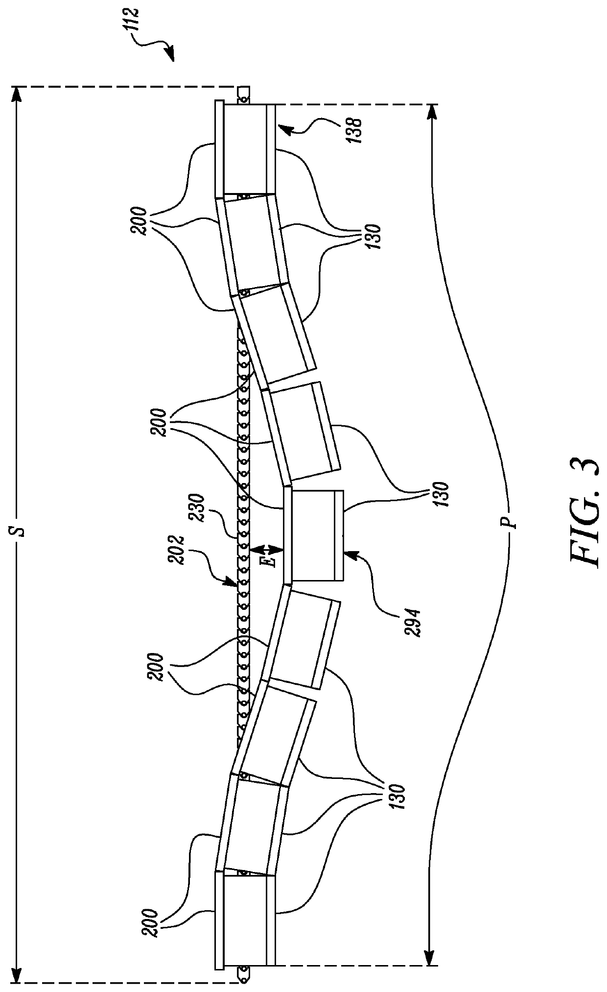
[0011]Referring to FIG. 1, a longwall mining machine 100 is shown. The longwall mining machine 100 may be operated within an underground mine 102, as shown. In one example, the longwall mining machine 100 may be used to mine materials, such as coal. Nevertheless, aspects of the present disclosure may be applied to other environments, and may not be limited to the environment set forth in the following description and / or drawings. The longwall mining machine 100 may include a face conveyor 108, a shearer 110, and a cable handling system 112.

[0012]Referring to FIGS. 1 and 2, the face conveyor 108 may be an armored face conveyor, and may be disposed and extended along a longwall face or a mine face 116 of the underground mine 102. For example, the face conveyor 108 may extend between a main gate end 120 and a tail gate end 122 (see FIG. 2) of the underground mine 102. The face conveyor 108 may include multiple face conveyor segments, referred to as pans 130. Adjacent pans 130 may be co...


PUM


Abstract

A cable handling system for a longwall mining machine is disclosed. The longwall mining machine includes a shearer configured to move along a pan line to mine material along a mine face. The cable handling system includes a service line configured to carry one or more supply lines to the shearer for facilitating shearer operation. Further, a plurality of interconnected trays accommodates the service line. Moreover, a controller is configured to determine a profile of the pan line; detect one or more parameters associated with the service line in relation to the profile of the pan line; and determine a likelihood of at least a portion of the service line dislodging from the plurality of interconnected trays based on the one or more parameters exceeding a predefined threshold.

Description

TECHNICAL FIELD[0001]The present disclosure generally relates to cable handling systems in longwall mining machines. More particularly, the disclosure relates to predicting a dislodgement of a service line of a cable handling system in a longwall mining machine.BACKGROUND[0002]Longwall mining machines generally include a shearer that traverses along an armored face conveyor (AFC) pan line to cut, extract, and obtain material, from a mine face. Lines supplying various requirements, including electrical power, may be extended to the shearer from a source. Generally, such lines are housed in a trailing cable handling system known as a bretby. The bretby is commonly constrained within a tray (or a plurality of trays) as part of the Longwall Pan line. As the shearer moves, the bretby is pulled and folded according to the direction of shearer travel, and during shearer operation, the bretby may be folded and stacked numerous times. As the stack of the bretby increases in height, so does t...

Claims


Application Information

Patent Timeline
IPC IPC(8): E21C35/04
CPCE21C35/046F16L3/01B65H75/04E21C35/00H02G11/00H02G11/006B65H2701/34F16L3/015H02G3/04E21F17/06E21C29/02E21C35/12E21C27/02E21C35/24
Inventor KIRKHOPE, EUAN RUSSELLSTANAWAY, BRADLEY
Owner CATERPILLAR INC
Why Eureka
Try Eureka