Conveyor pan with improved edge shaping

a conveyor pan and edge shaping technology, applied in the direction of cutting machines, earthwork drilling and mining, transportation and packaging, etc., can solve the problems of conveyor pan fines, mechanical equipment of all forms are subjected to extreme shock ranges, mechanical twisting, racking and concentrated stresses, etc., to improve the fatigue life of conveyor pans, reduce conveyor pan fines, and reduce stress levels

Active Publication Date: 2011-03-01
JOY GLOBAL UNDERGROUND MINING LLC
View PDF6 Cites 4 Cited by
  • Summary
  • Abstract
  • Description
  • Claims
  • Application Information

AI Technical Summary

Benefits of technology

[0009]Another of the principal objects of the invention is to delay and smooth shearer load transfer from conveyor pan to conveyor pan.
[0017]Another of the principal objects of the invention is to reduce problems caused by misalignment of adjacent conveyor pan section ends. Any change in perfect alignment is more readily accommodated by the conveyor pan section ends of this invention.

Problems solved by technology

The operating environment of a mine is extremely harsh on mechanical equipment of all forms.
Moreover, the abrasive material is fluidized in the presence of water and contaminated oil.
In addition to the abrasive and corrosive nature of the environment, the machinery is subjected to extreme ranges of shock, mechanical twisting, racking and concentrated stresses due to uneven support surfaces.

Method used


Image

  • Conveyor pan with improved edge shaping
  • Conveyor pan with improved edge shaping
  • Conveyor pan with improved edge shaping

Examples


Embodiment Construction

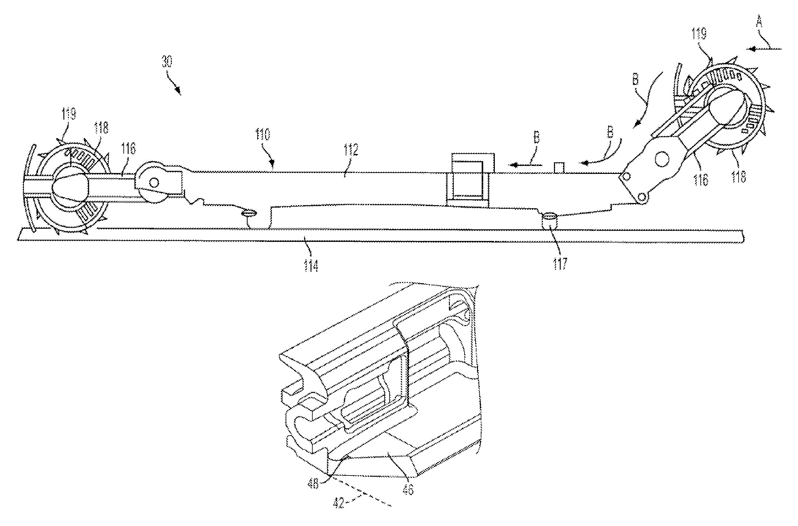
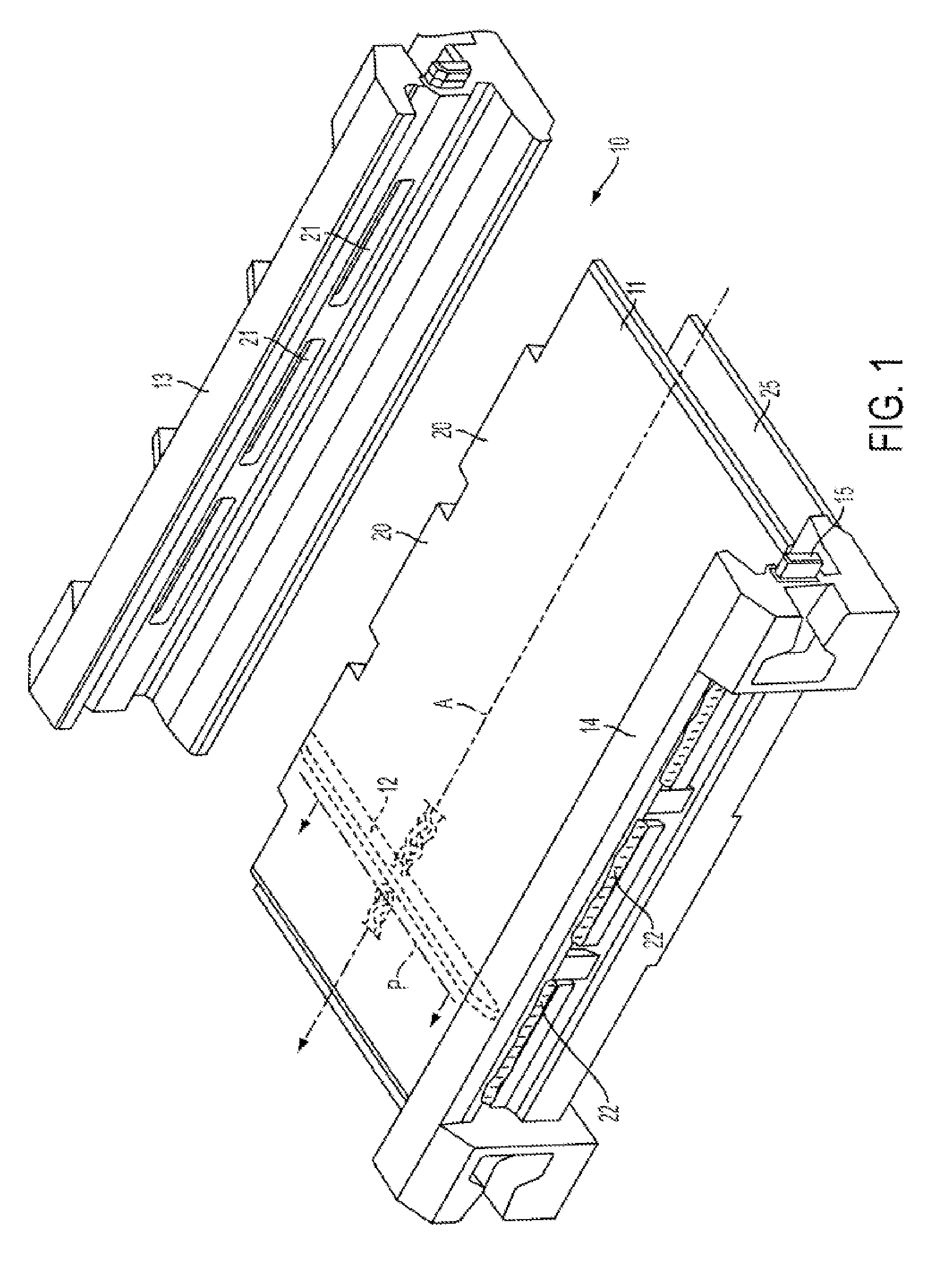
[0027]As illustrated in FIG. 1 of the drawings, the invention includes a longwall mine face conveyor pan assembly 10 especially adapted for use with an armored face conveyor system for handling coal or the like. An elongated deck plate 11 serves to define the coal production feed path P along the longitudinal axis A of the conveyor system. As is conventional, the feeding of the coal along the conveyor pan assembly 10 is by a scraper chain with individual flights 12; one shown in dashed line outline in FIG. 1.

[0028]A pair of parallel side rails or members 13 and 14, preferably formed as sigma sections and extending along opposite sides of the deck plate 11, further define the material feed path P. The sigma section rail profile is a standard of the industry to provide concave guide walls for the scraper chain flights 12. The upper walls are in direct contact with the aggregate material scraped along by the upper chain flights whereas the lower concave walls guide and align the flight...


PUM


Abstract

A conveyor pan for use with a shearer with a skid-type shoe in a longwall mining operation, the conveyor pan including a side member having a surface adapted to be engaged by the shearer skid-type shoe, the surface being formed by a piece of the side member that extends horizontally for the length of the side member. The piece has a first end and a second end, each piece end having a top, a rear, a front and an edge. The first end edge and the second end edge are each formed by each edge being between 45 degrees removed from a vertical plane extending at 90 degrees to the horizontal plane formed by the side member surface.

Description

BACKGROUND OF THE INVENTION[0001]This invention relates to a conveyor pan assembly for an armored face conveyor, such as for handling coal in a longwall face mining system.[0002]A variety of different apparatuses exist for mining coal and other materials from underground seams. One apparatus is a continuous mining machine used in instances where extended portions or longwalls of seam are mined. Such longwalls may, depending upon the seam configuration, extend for distances of 300-1200 or more feet. It is standard practice in this type of mining to mine parallel entries into the seam to be mined and connect those entries with one or more primary passages. Such arrangement defines the longwall faces to be mined. The roof of the primary passages are usually supported by movable roof supports during the mining of the exposed “face” of the longwall pillar.[0003]Conventional longwall mining techniques employ a mining machine that is known in the industry as a longwall shearer. A longwall ...

Claims


Application Information

Patent Timeline
Patent Type & Authority Patents(United States)
IPC IPC(8): E21C35/12
CPCB65G19/285B65G19/28E21C35/12
Inventor TOUT, JOHNPOWELL, GORDON EDMUND
Owner JOY GLOBAL UNDERGROUND MINING LLC
Why Eureka
Try Eureka