Hydraulic circuit for longwall mining

A technology of hydraulic circuit and working surface, applied in the field of hydraulic circuit, can solve the problems of undesired opening and backflow blocking, and achieve the effect of high cost performance, high cost performance and durability

Inactive Publication Date: 2012-10-03
TIEFENBACH CONTROL SYST
View PDF12 Cites 3 Cited by
  • Summary
  • Abstract
  • Description
  • Claims
  • Application Information

AI Technical Summary

Problems solved by technology

[0007] Causes may be: leaky valves that release pressure applied to the support or working cylinders of the shield; open valves and / or stuck open valves; stuck open preset valves; backflow blockages that- Depending on the area ratio of the control piston - this can lead to undesired opening of the safety valve or load support valve / blockable check valve and / or flushing out of the cylinder / piston unit

Method used


Image

  • Hydraulic circuit for longwall mining
  • Hydraulic circuit for longwall mining
  • Hydraulic circuit for longwall mining

Examples


Embodiment Construction

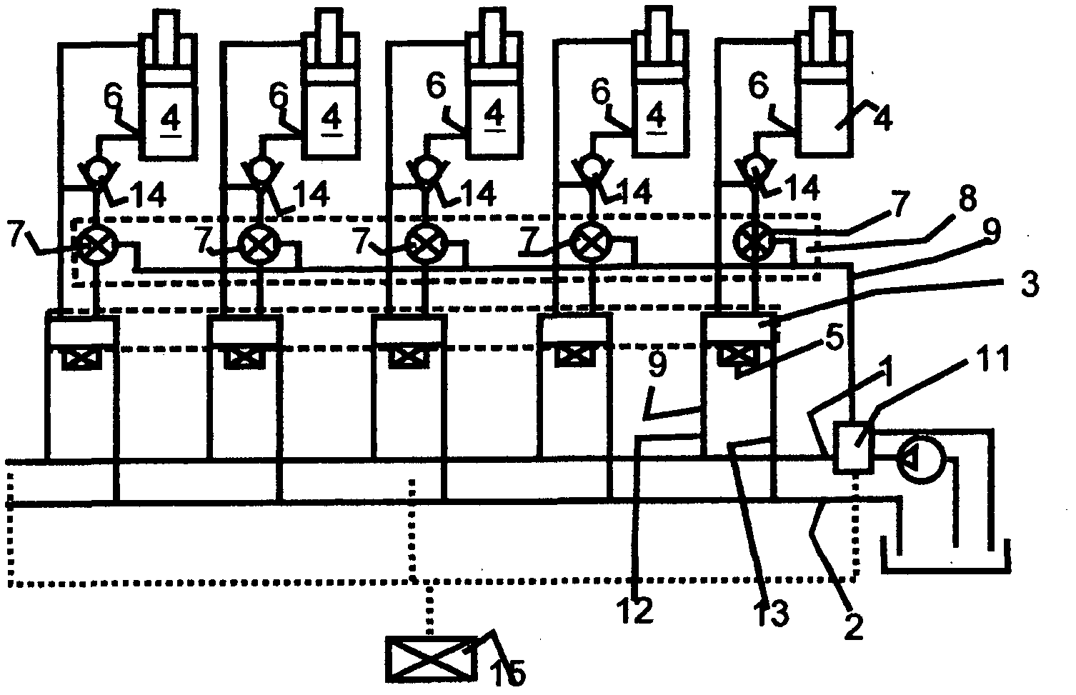
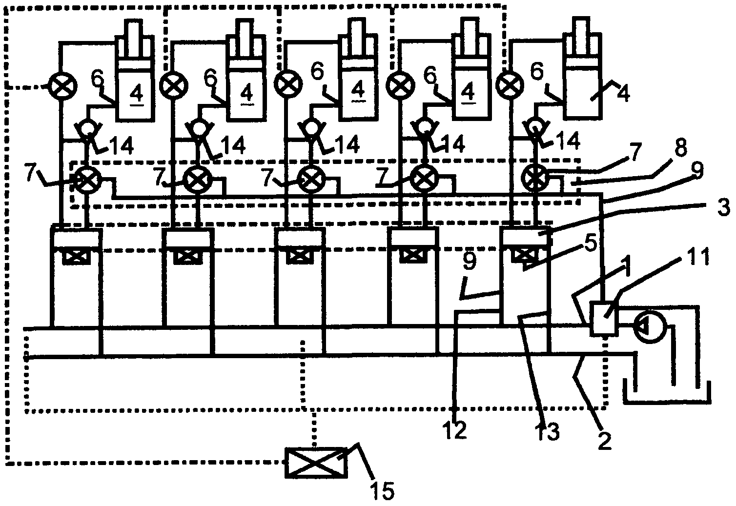
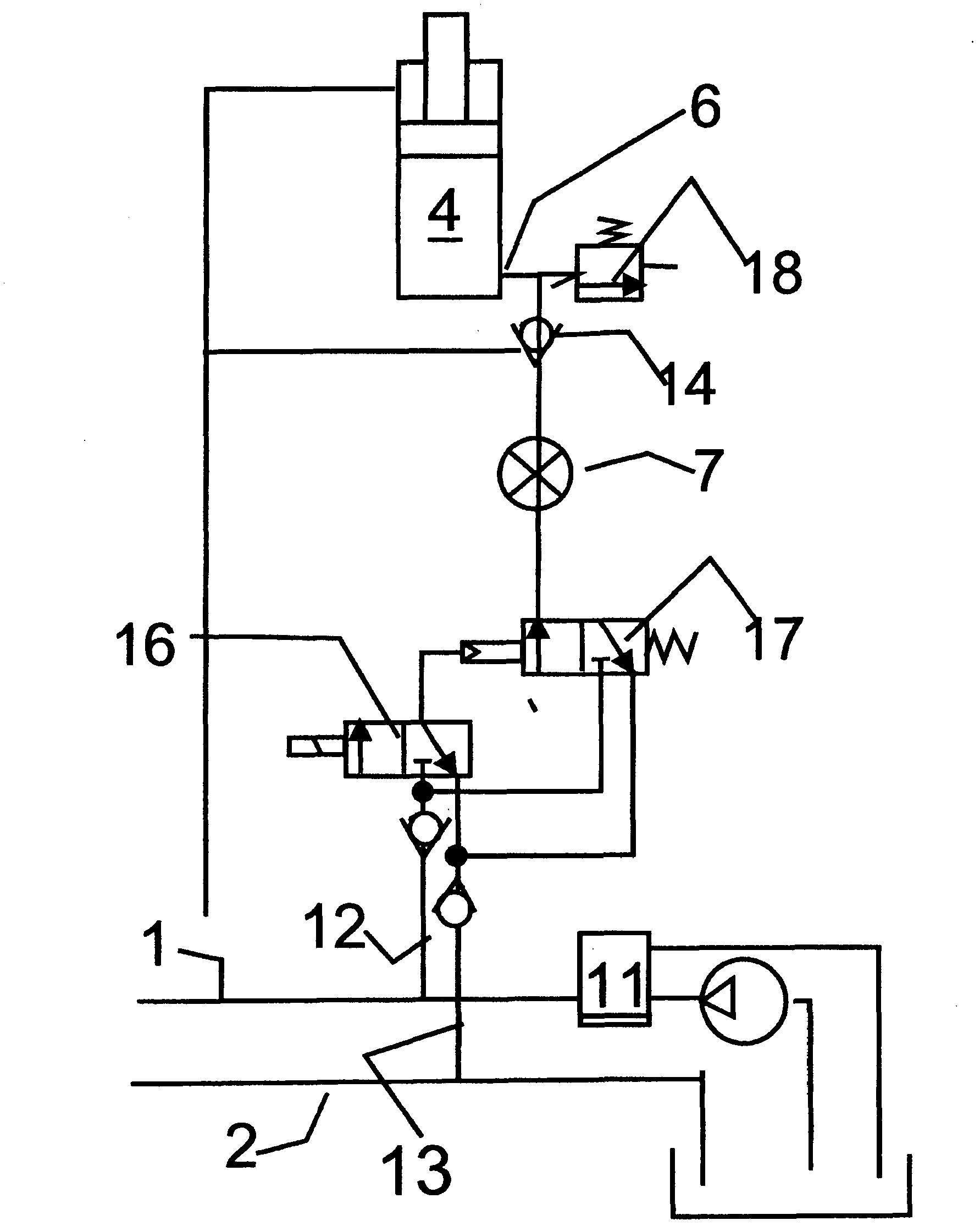
[0029] Basically, the connection of each force applicator to the pump accumulation line of the face (pump branch) is via a non-return valve configured as a blockable block between the output of the force applicator, which is loaded by the mountain pressure, and the hydraulic control device 5 The load support valve 14 is blocked, so that when the pump pressure is canceled or cut off, the load pressure of the force applicator falls on the check valve which is sealed closed. However, the non-return valve 14 can be blocked by hydraulic presetting by the system pressure when the pressure difference between the load pressure and the presetting pressure falls below a value predetermined by the valve design. The non-return valve 14 is switched hydraulically, so that when the hydraulic pressure is cut off, the working space of the force applicator is connected to the return flow accumulation line via the starter 6 and the return flow branch. Such a shut-off non-return valve is known, f...


PUM


Abstract

A hydraulic circuit for longwall support for use in underground mining for supporting a longwall by means of a plurality of support shields comprises a pressure monitoring device in the pressure line between the load maintaining valve and the shield control valve. Said pressure monitoring device can be a device for monitoring the piston position of the shield control valve which device signals a deviation of the set position predetermined by the shield control device from the measured actual position of the piston of the shield control valve in the form of a deviation signal. It may also be a pressure sensor which signals the deviation of the set pressure predetermined by the shield control device from the measured actual pressure in the form of a deviation signal. Signaling can be acoustic or optical.

Description

technical field [0001] The invention relates to a hydraulic circuit according to the preamble of claim 1 , which is used for face support in underground mining by means of a support device (shield support). Background technique [0002] Such circuits are well known and widely used, involving hydraulic equipment controlled by their own pressure. In such hydraulic systems, the valves are preadjusted hydraulically by using the pump pressure of the hydraulic circuit. This method is realized in the support control (Ausbausteuerung). Even just two supply lines in the face support will suffice. In contrast, in external control systems the hydraulic presetting command is generated by a separate control valve which works independently of the load pressure or the pump pressure, wherein the control valve is supplied with pressure medium via a separate pressure line. Furthermore, such a system must also include separate return lines for all control volumes. However, this also increa...

Claims


Application Information

Patent Timeline
Patent Type & Authority Applications(China)
IPC IPC(8): E21D23/26
CPCE21D23/18E21D23/26F15B19/005Y10T137/8158
Inventor W・威格尔G・乌尔芬格P・拉姆斯
Owner TIEFENBACH CONTROL SYST
Why Eureka
Try Eureka