Method for controlling longwall mining operations

a mining operation and longwall technology, applied in the direction of mining structures, mine roof supports, slitting machines, etc., can solve the problems of no longer advanced shield support frames, blocked canopy/gob shields, and no longer be advanced shields, so as to eliminate the vibration of components. , the effect of eliminating errors

Inactive Publication Date: 2014-03-18
RAG AG
View PDF12 Cites 4 Cited by
  • Summary
  • Abstract
  • Description
  • Claims
  • Application Information

AI Technical Summary

Benefits of technology

[0023]According to one exemplary embodiment of the invention, it is provided that acceleration sensors are used as the inclination sensors, which detect the angle of the acceleration sensor in space via the deviation from Earth's gravity. It can be provided, to eliminate errors caused by the vibrations of the components used, that the measured values ascertained by the acceleration

Problems solved by technology

The danger of placement of the overlying strata exists if, when convergence is beginning, the shield props are entirely retracted and, because of the overlying strata, which then applies a load, the shield support frame is blocked and can no l

Method used


Image

  • Method for controlling longwall mining operations
  • Method for controlling longwall mining operations
  • Method for controlling longwall mining operations

Examples


Embodiment Construction

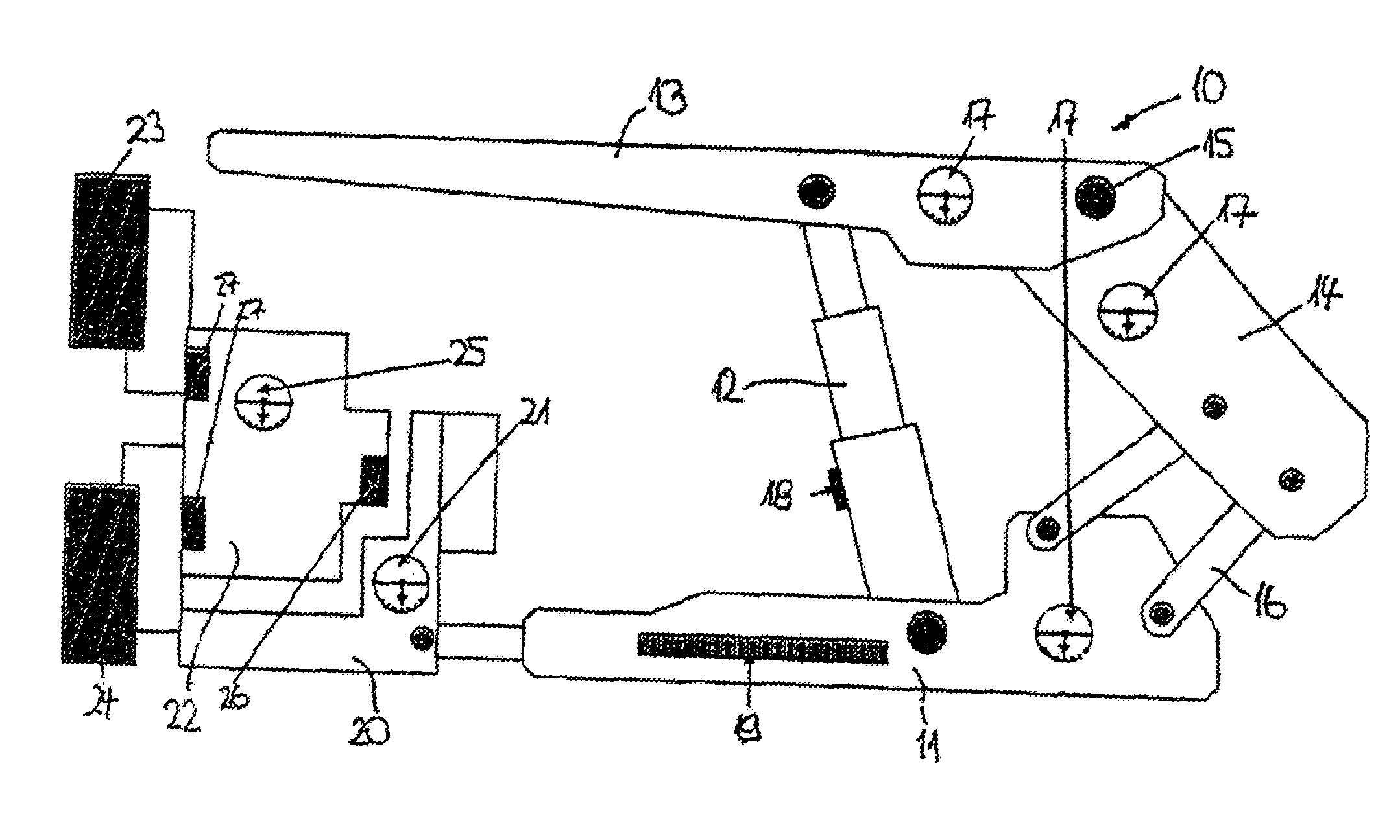
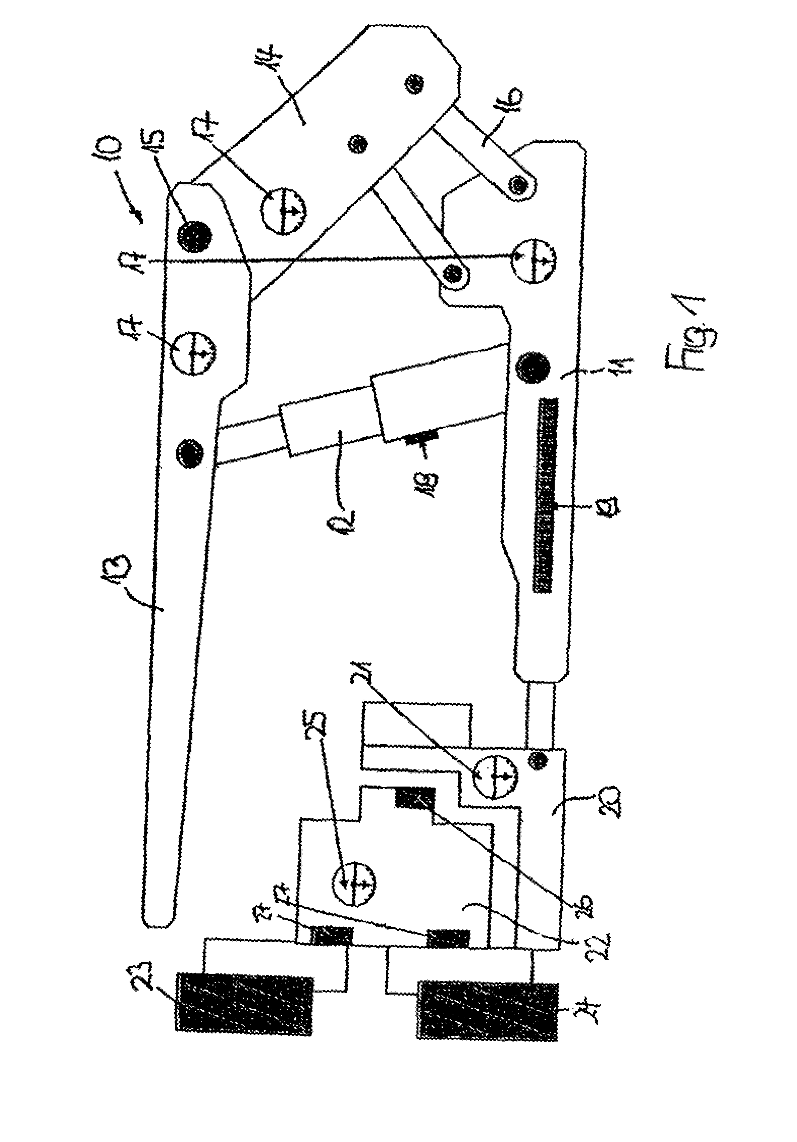
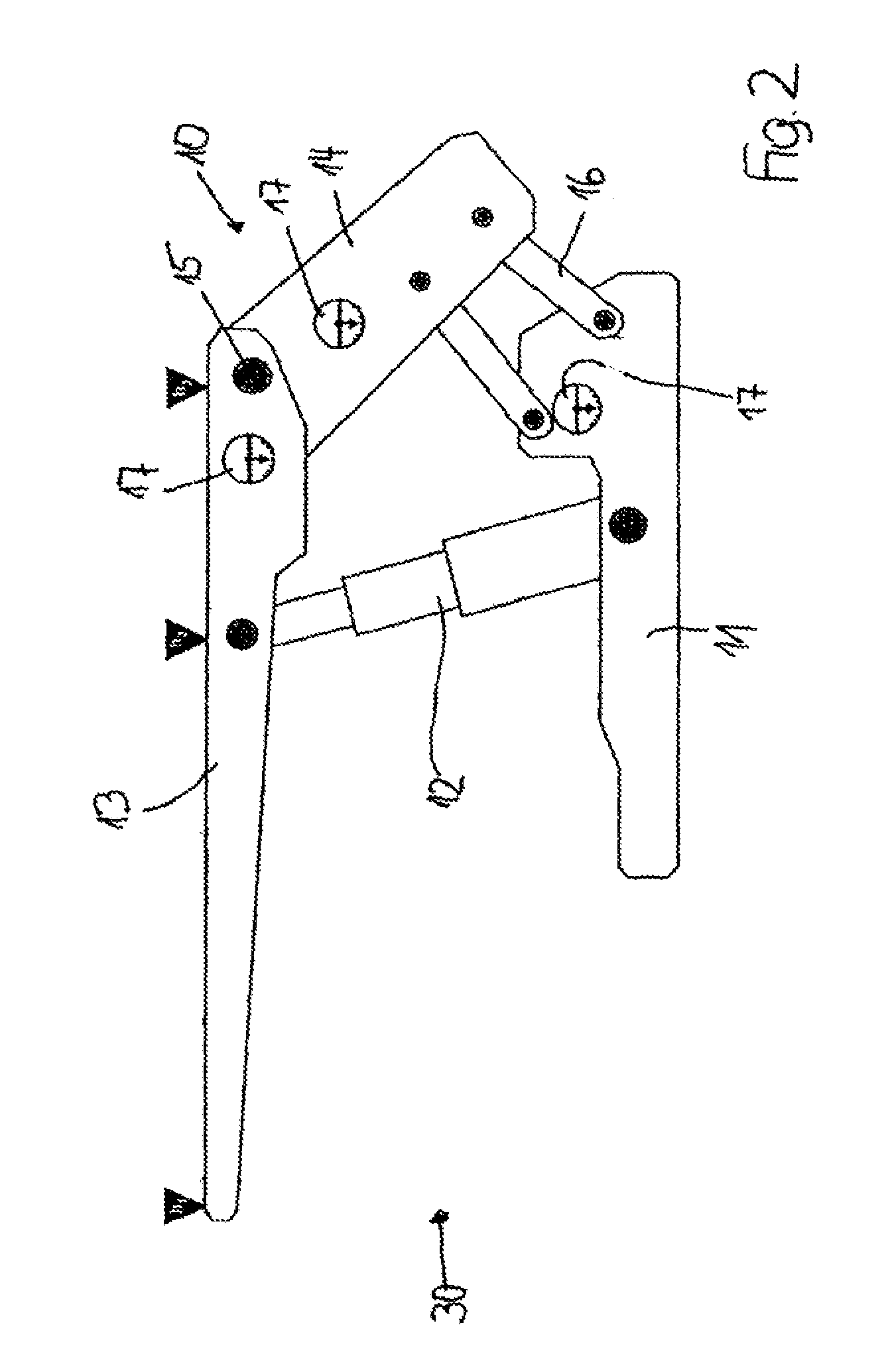
[0034]The longwall equipment shown in FIG. 1 primarily comprises a shield support frame 10 having a floor skid 11, on which two props 12 are attached in a parallel configuration, of which only one prop is recognizable in FIG. 1, which carries a top canopy 13 on its upper end. While the top canopy 13 protrudes in the direction of the extraction machine (to be described hereafter) at its front (left) end, a gob shield 14 is linked on the rear (right) end of the top canopy 13 using a joint 15, the gob shield being supported by two supporting connection rods 16, which rest on the floor skid 11 in the side view. In the exemplary embodiment shown, three inclination sensors 17 are attached to the shield support frame 10, one inclination sensor 17 on the floor skid 11, one inclination sensor 17 in the rear end of the top canopy 13 in proximity to the joint 15, and one inclination sensor 17 on the gob shield 14. As is not shown in greater detail, an inclination sensor can also be provided on...


PUM


Abstract

A method for controlling a longwall mining operation, including a face conveyor, at least one extraction machine, and a hydraulic shield support, in underground coal mining. Using inclination sensors disposed on at least three of the four main components of each shield support frame, such as floor skid, gob shield, support connection rods, and gob-side region of the top canopy, the inclination of the shield components relative to horizontal is ascertained in the direction of step. In a computer, the ascertained inclination data is compared with base data stored in the computer that defines the geometrical orientation of the components and their movement during stepping. From the comparison, a respective height of the shield support frame, at the forward end of the top canopy, is calculated as a measure for the face opening.

Description

BACKGROUND OF THE INVENTION[0001]The instant application should be granted the priority dtaes of Feb. 19, 2008, the filing date of the International patent application PCT / EP2008 / 001262.[0002]The invention relates to a method for controlling longwall operations in underground coal mining having a face conveyor, at least one extraction machine, and a hydraulic shield support.[0003]The control of longwall operations during face advancing generally is concerned with the best possible exploitation of the provided machine capacities while avoiding shutdowns, an automation of the required control procedures being provided if possible, in order to avoid flawed human decisions. Approaches to automation of the control are in development and / or already in use, such as sensory boundary layer detection / control, learning step methods, recognition and control of the advancing path of the hydraulic supports, automated stepping of the hydraulic supports, and automatic maintenance of a predefined ta...

Claims


Application Information

Patent Timeline
IPC IPC(8): E21D23/16E21D9/093E21C35/08
CPCE21D23/12E21C35/12
Inventor JUNKER, MARTINMOZAR, ARMIN
Owner RAG AG
Why Eureka
Try Eureka