Reducing Device Overlay Errors

a technology of process overlay and error reduction, applied in semiconductor/solid-state device testing/measurement, semiconductor/solid-state device details, instruments, etc., can solve the problem that the effect of process overlay errors becomes ever more significan

Pending Publication Date: 2020-01-30
KLA TENCOR TECH CORP
View PDF7 Cites 2 Cited by
  • Summary
  • Abstract
  • Description
  • Claims
  • Application Information

AI Technical Summary

Benefits of technology

[0003]The following is a simplified summary providing an initial understanding of the invention. The summary does not necessarily identify key elements nor limits the scope of the invention, but merely serves as an introduction to the following description.

Problems solved by technology

As node size in semiconductors manufacturing decreases, the effect of process overlay errors becomes ever more significant.

Method used


Image

  • Reducing Device Overlay Errors
  • Reducing Device Overlay Errors
  • Reducing Device Overlay Errors

Examples


Embodiment Construction

[0013]In the following description, various aspects of the present invention are described. For purposes of explanation, specific configurations and details are set forth in order to provide a thorough understanding of the present invention. However, it will also be apparent to one skilled in the art that the present invention may be practiced without the specific details presented herein. Furthermore, well known features may have been omitted or simplified in order not to obscure the present invention. With specific reference to the drawings, it is stressed that the particulars shown are by way of example and for purposes of illustrative discussion of the present invention only, and are presented in the cause of providing what is believed to be the most useful and readily understood description of the principles and conceptual aspects of the invention. In this regard, no attempt is made to show structural details of the invention in more detail than is necessary for a fundamental u...


PUM

PropertyMeasurementUnit
periodic structuresaaaaaaaaaa
periodic structureaaaaaaaaaa
sizeaaaaaaaaaa

Abstract

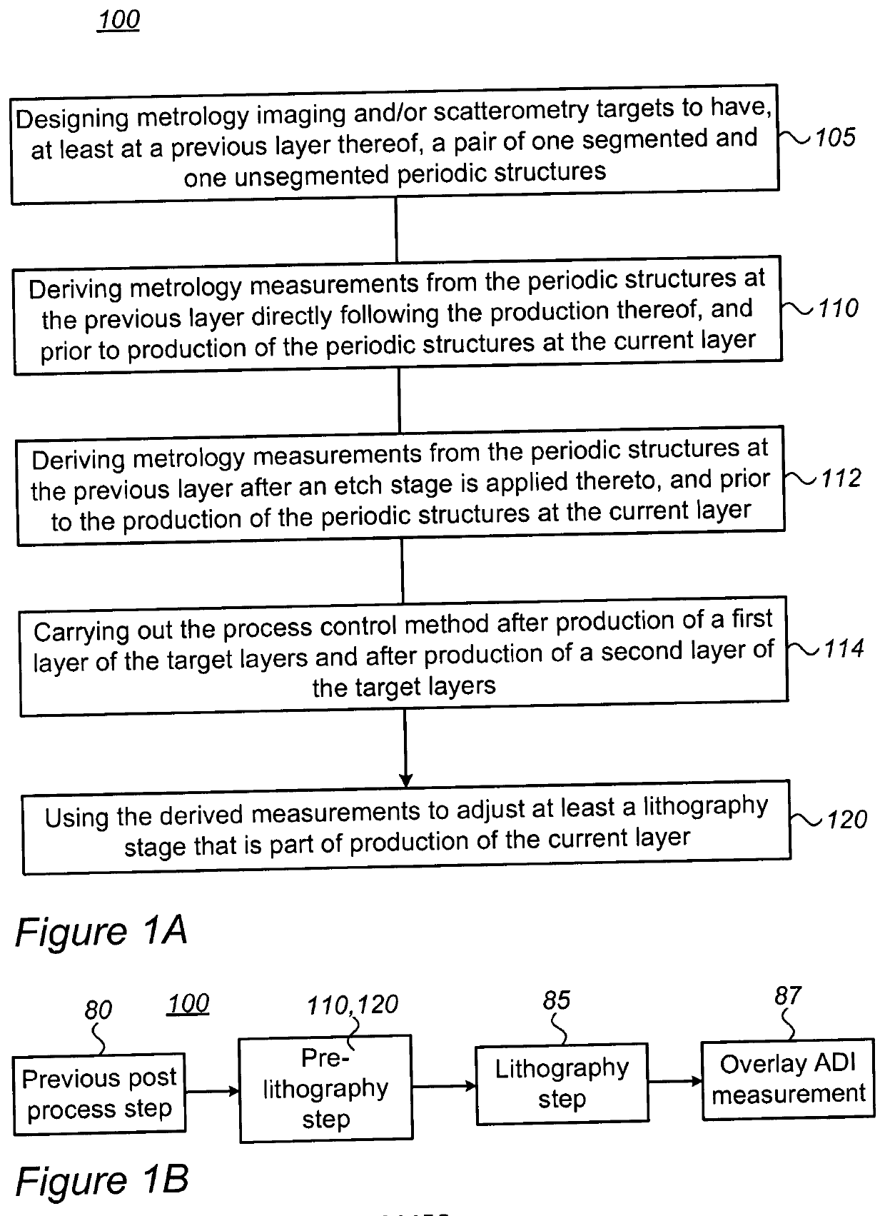
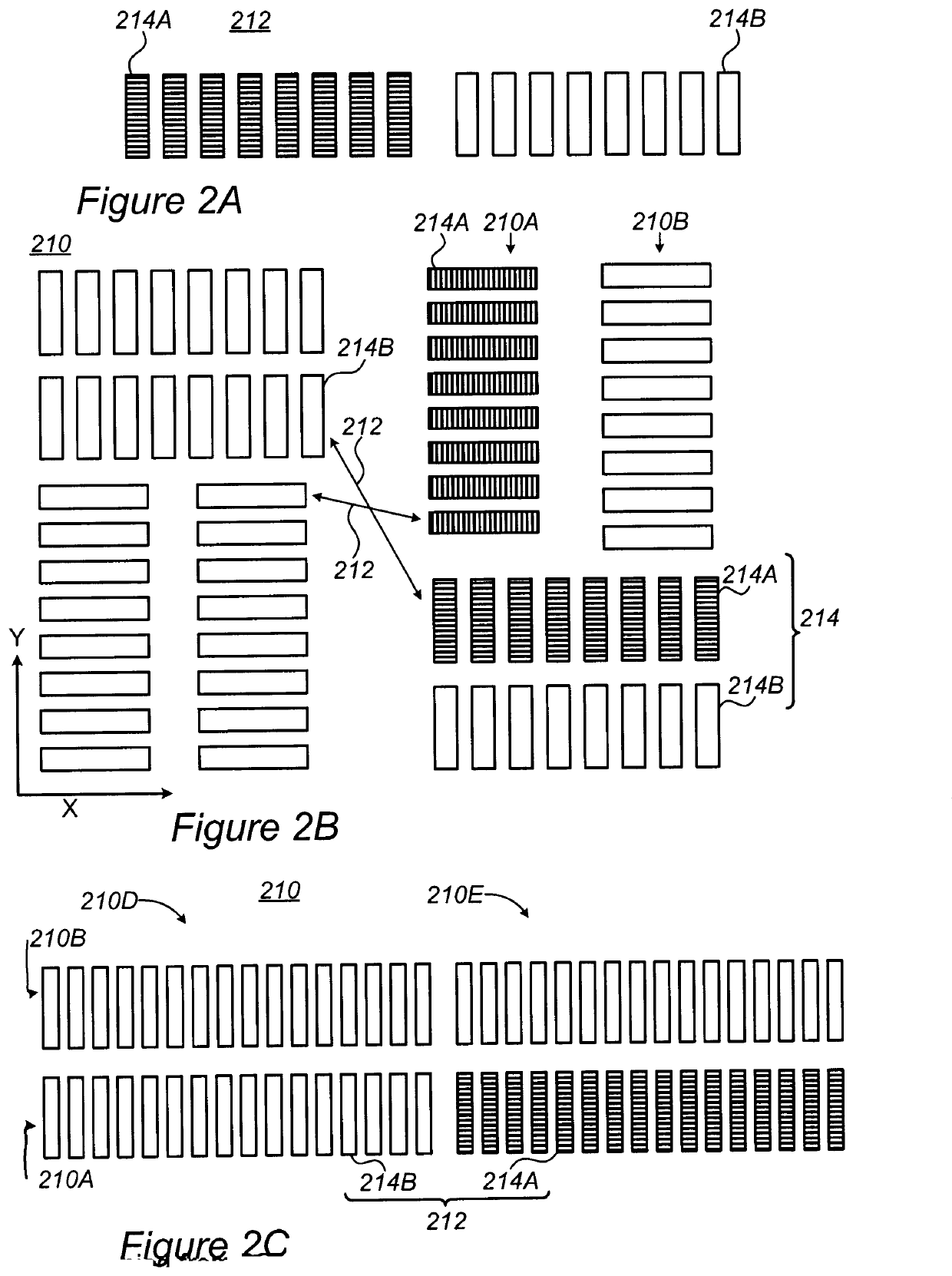
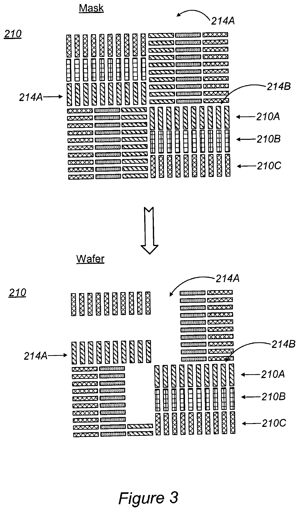
Process control methods, metrology targets and production systems are provided for reducing or eliminating process overlay errors. Metrology targets have pair(s) of periodic structures with different segmentations, e.g., no segmentation in one periodic structure and device-like segmentation in the other periodic structure of the pair. Process control methods derive metrology measurements from the periodic structures at the previous layer directly following the production thereof, and prior to production of the periodic structures at the current layer, and use the derived measurements to adjust lithography stage(s) that is part of production of the current layer. Production system integrate lithography tool(s) and metrology tool(s) into a production feedback loop that enables layer-by-layer process adjustments.

Description

BACKGROUND OF THE INVENTION1. Technical Field[0001]The present invention relates to the field of semiconductor metrology, and more particularly, to elimination or reduction of process overlay error.2. Discussion of Related Art[0002]As node size in semiconductors manufacturing decreases, the effect of process overlay errors becomes ever more significant.SUMMARY OF THE INVENTION[0003]The following is a simplified summary providing an initial understanding of the invention. The summary does not necessarily identify key elements nor limits the scope of the invention, but merely serves as an introduction to the following description.[0004]One aspect of the present invention provides a process control method utilizing a metrology target having periodic structures at least at a previous layer and at a current layer of a wafer in lithographic preparation, the process control method comprising: deriving metrology measurements from the periodic structures at the previous layer directly follow...

Claims


Application Information

Patent Timeline
Patent Type & Authority Applications(United States)
IPC IPC(8): G03F7/20H01L23/544H01L21/68G01B11/27
CPCH01L21/681H01L2223/54426H01L2223/5442H01L23/544G01B2210/56G01B11/272G03F7/70633G03F7/70683H01L22/12H01L22/20H01L22/30
Inventor YERUSHALMI, LIRANVOLKOVICH, ROIE
Owner KLA TENCOR TECH CORP
Why Eureka
Try Eureka