Machine for depositing and dispensing coins

a machine and coin technology, applied in coin/currency accepting devices, coin dispensers, coin counters, etc., can solve the problem of regular refilling of internal hoppers, and achieve the effect of optimizing the content of internal hoppers and simplifying the management of coins

Active Publication Date: 2020-01-30
CIMA SRL
View PDF0 Cites 8 Cited by
  • Summary
  • Abstract
  • Description
  • Claims
  • Application Information

AI Technical Summary

Benefits of technology

[0015]The general purpose of the present disclosure is to avoid the aforementioned drawbacks by supplying a machine for depositing and dispensing coins that makes it possible to simplify the management of the coins during the depositing and dispensing steps and to optimize the content of its internal hoppers.
[0016]A further purpose of the disclosure is to avoid possible situations that can lead to the shutdown of the machine due to a lack or excess of coins of a certain denomination.
[0017]In particular, a purpose of the disclosure is to make it possible to manage the excess coins in the hoppers both as a mix of coins of various denominations collected in a single container, and as quantities of coins divided by denomination, which can be advantageously stored securely at the same manager of the machine and used when necessary to restore the level of coins in specific hoppers, for example at the moments of maximum demand for dispensing by cashiers.

Problems solved by technology

These machines have the drawback that the deposited coins must then be removed from the respective internal hoppers, taken into the custody of workers authorized and trained in the transportation of valuables (CIT, or Cash-In-Transit) and finally managed in suitable ways for subsequent use at other locations.
Also in these machines the main drawback is that the internal hoppers must be regularly refilled with coins of the various denominations by workers specialized in the transportation of valuables.

Method used


Image

  • Machine for depositing and dispensing coins
  • Machine for depositing and dispensing coins
  • Machine for depositing and dispensing coins

Examples


Embodiment Construction

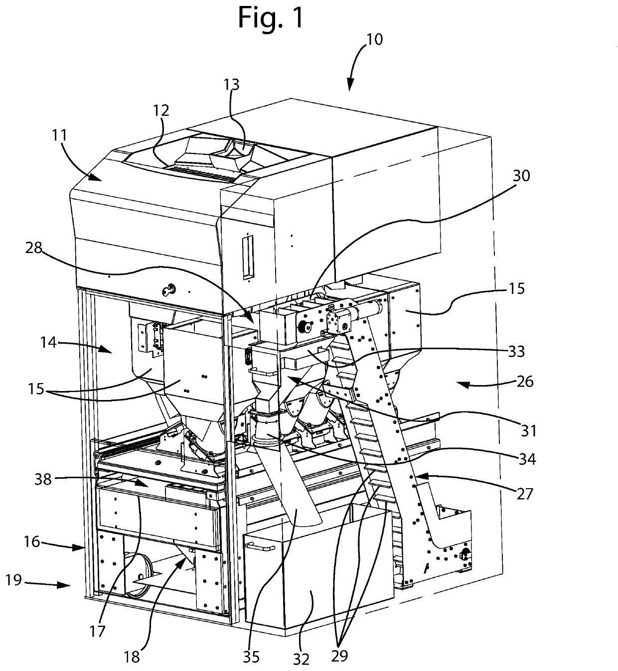
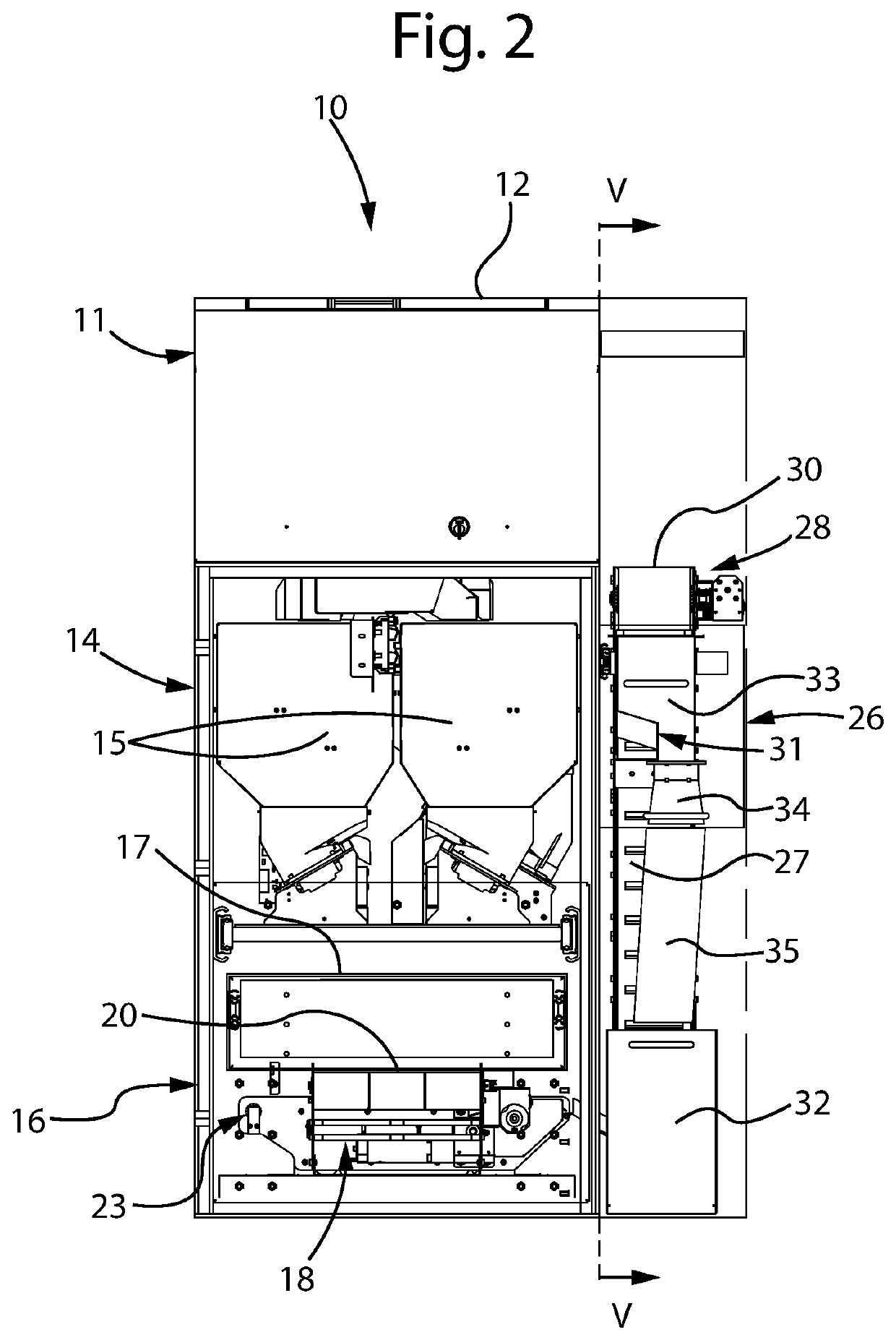
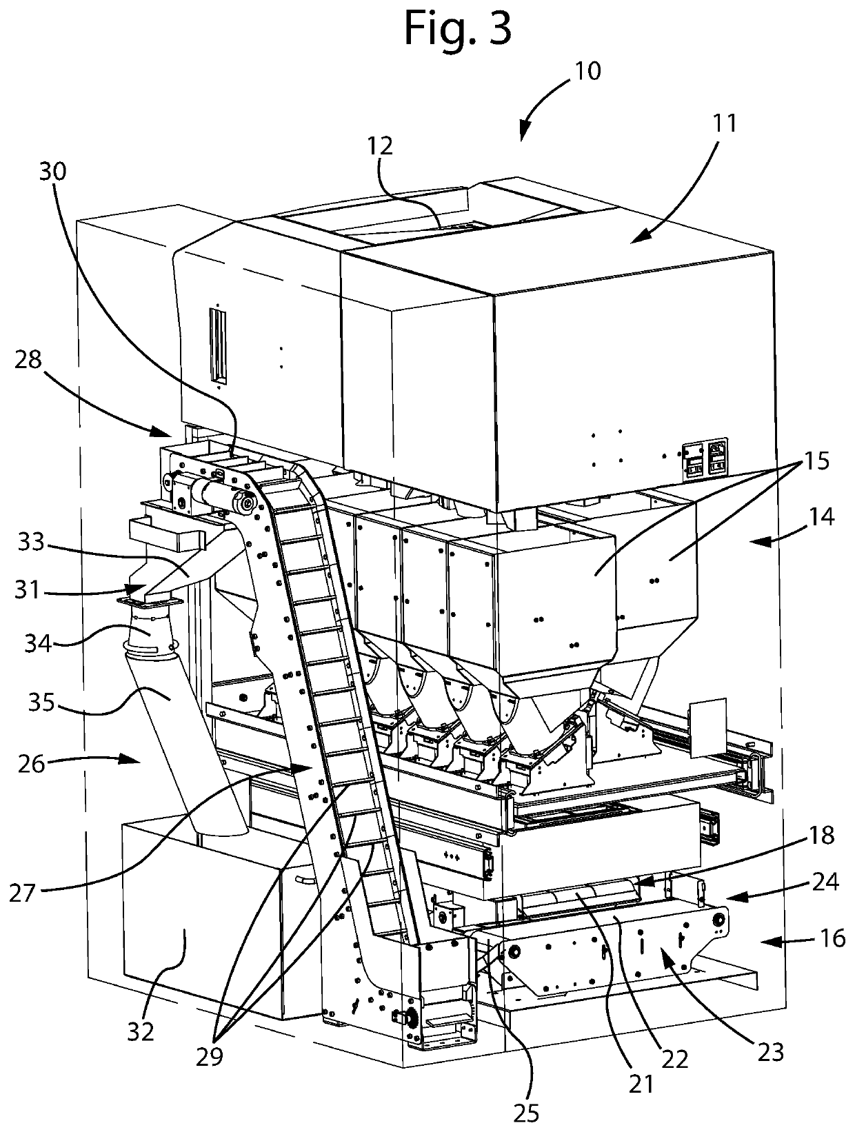
[0031]With reference to the figures, FIG. 1 illustrates a machine 10 for depositing and dispensing coins according to the disclosure.

[0032]The machine 10 generically comprises a first upper portion 11 in which there is a tray 12 for receiving the coins deposited by the user (typically a cashier at end of shift, who must empty his / her own till) and an opening 13 for introducing coins inside the machine. Advantageously, the tray 12 is liftable and tiltable so as to make the coins contained in it flow directly towards the introduction opening 13.

[0033]Inside the upper portion 11 of the machine there are also (not shown in detail in the figures, since they are devices well known to those skilled in the art) means for recognizing and verifying the coins and for sorting them based on denomination.

[0034]With the exception of said first upper portion 11, in the attached figures the machine is in general graphically represented with the outer walls partially “transparent” to make it possible...


PUM


Abstract

A machine for depositing and dispensing coins includes a first portion containing devices for reception of the deposited coins and for recognition and sorting of the coins based on the denomination thereof, a second portion) containing a plurality of internal hoppers configured to selectively contain the coins sorted by denomination and a third portion containing coin processing means for processing the coins in the dispensing step, a seat being present in the third portion for the temporary housing of a till configured to be filled with predetermined compositions of coins of the various denominations coming from the internal hoppers, the machine further including coin conveying means adapted to receive, at the seat, coins coming from the internal hoppers or from the recognition and sorting devices and to convey them to a higher zone of the machine, where a coin path selector is disposed at the end of the coin conveying means to the higher zone of the machine, the coin path selector being movable between a first position where it enables the conveyance of the coins into an internal collection container and a second position wherein it enables the dispensing of the coins outside the machine.

Description

CROSS REFERENCE TO RELATED APPLICATIONS[0001]This application is related to and claims the benefit of Italian Patent Application No. 102018000007620 filed on Jul. 30, 2018 and Italian Patent Application No. 102018000010640 filed on Nov. 28, 2018, the entire contents of which are incorporated herein by reference in their entirety.TECHNICAL FIELD[0002]The present disclosure refers to a machine for managing coins, in particular adapted to receive and dispense coins, tokens or similar.BACKGROUND[0003]In the prior art machines capable of receiving and storing valuables inside them, for example coins, deposited by an operator are used. These machines, usually called “coin deposit machines”, are generally provided with a portion for accepting the coins introduced by the user, a system for recognizing and sorting the coins based on their denomination and a plurality of internal hoppers for containing the coins sorted by denomination.[0004]A typical example of use of these machines is in the...

Claims


Application Information

Patent Timeline
Patent Type & Authority Applications(United States)
IPC IPC(8): G07D3/00G07D1/00
CPCG07D1/00G07D3/00G07D9/04G07D9/06G07D11/00
Inventor RAZZABONI, NICOLETTARAZZABONI, VITTORIO
Owner CIMA SRL
Why Eureka
Try Eureka