Rotary electric machine and vehicle carrying rotary electric machine

a rotary electric machine and electric motor technology, which is applied in the direction of magnetic circuits, magnetic circuits, rotating parts, etc., can solve the problems of increasing weight and size of rotary electric machines, and achieve the effect of increasing weight and size and high efficiency of operation

Inactive Publication Date: 2020-01-30
HONDA MOTOR CO LTD
View PDF0 Cites 0 Cited by
  • Summary
  • Abstract
  • Description
  • Claims
  • Application Information

AI Technical Summary

Benefits of technology

[0010]The present invention may make it possible to produce, without causing the weight

Problems solved by technology

Unfortunately, in order to achieve a highly efficient operation by using a variable field, the variable-field rotary electric machine according to JP2010-057209A needs an additional actuator for di

Method used


Image

  • Rotary electric machine and vehicle carrying rotary electric machine
  • Rotary electric machine and vehicle carrying rotary electric machine
  • Rotary electric machine and vehicle carrying rotary electric machine

Examples


Embodiment Construction

[0036]With reference to the appropriate Drawings, the following details rotary electric machines and a vehicle carrying each rotary electric machine according to embodiments of the present invention.

[0037]Note that in the following figures, the same members or corresponding members have the same reference numerals. In addition, the size and shape of each member may be modified or schematically exaggerated for description convenience.

[0038][Basic Structure of Rotary Electric Machine 11 According to the Present Invention]

[0039]First, with reference to FIGS. 1A to 1L, the following details the basic structure of a rotary electric machine 11 according to an embodiment of the present invention.

[0040]FIG. 1A is a front view of the rotary electric machine 11 according to this embodiment.

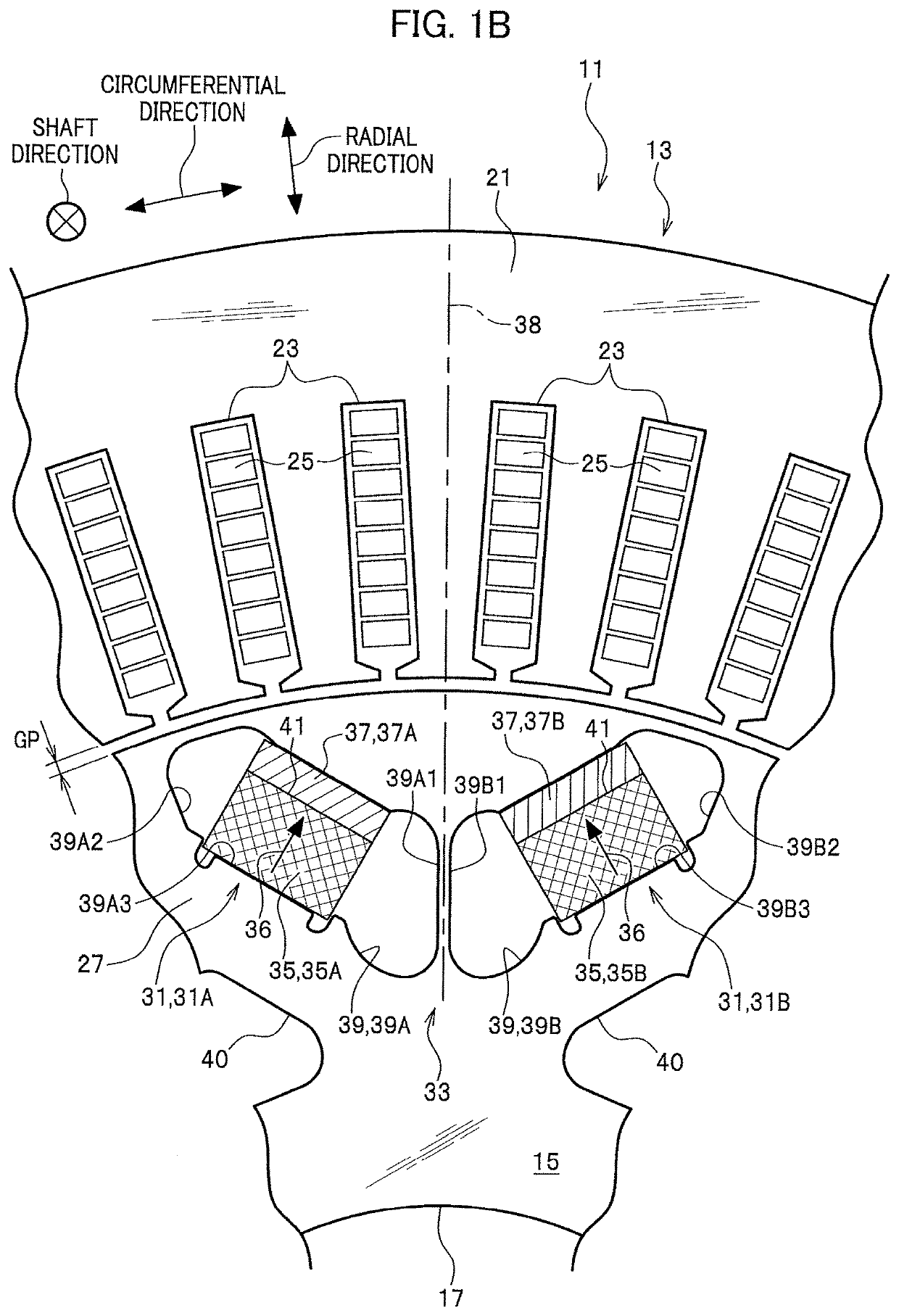
[0041]FIG. 1B is a magnified view of surroundings of a magnetic pole section 33 provided in a rotor 15 included in the rotary electric machine 11 illustrated in FIG. 1A.

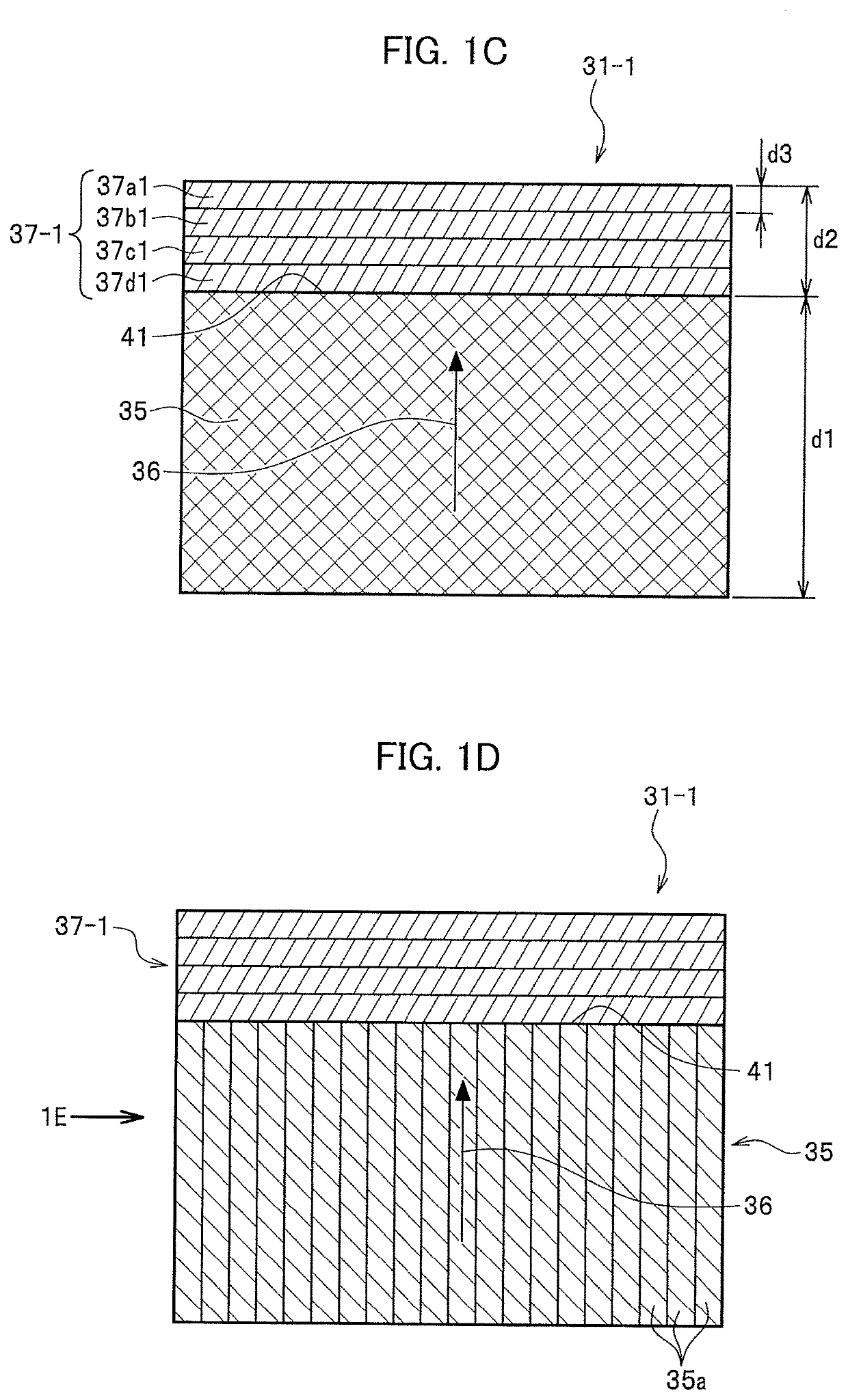
[0042]FIG. 1C is a magnified front vi...


PUM


Abstract

A rotary electric machine is provided which includes: an annular stator comprising a stator core and coils included in the stator core; and an annular rotor comprising a rotor core and a plurality of housing holes for magnetic bodies extending in a drive shaft direction, the housing holes being arranged in a circumferential direction, the rotor facing, via a gap, an inner periphery of the stator. Each magnetic body includes a hard magnetic body and a soft magnetic body. The soft magnetic body is stacked in a magnetization direction of the hard magnetic body. Each housing hole houses the magnetic body comprising the hard magnetic body and the soft magnetic body.

Description

TECHNICAL FIELD[0001]The present invention relates to a highly efficient operation-achievable rotary electric machine and a vehicle carrying the rotary electric machine.BACKGROUND ART[0002]Nowadays, to address the problem of realizing low-carbon societies, widely used are vehicles carrying a rotating electric machine in addition to or instead of an internal-combustion engine as a driving source of each vehicle. Examples of the vehicles include what is called hybrid electric vehicles and electric vehicles.[0003]Each rotary electric machine includes an annular stator and a cylindrical rotor. The stator includes a stator core provided with a plurality of slots, each slot having a stator coil. The rotor is rotatably provided via a small gap to an inner periphery of the stator. The rotor includes a rotor core provided with a plurality of permanent magnets placed with an equal distance in the circumferential direction thereof.[0004]In the rotary electric machine, when a motor current flow...

Claims


Application Information

Patent Timeline
IPC IPC(8): H02K1/27H02K1/16
CPCH02K29/03H02K1/2766H02K1/16H02K21/021H02K21/14H02K1/02
Inventor KUBOTA, YOSHIHISAITO, YUTA
Owner HONDA MOTOR CO LTD
Why Eureka
Try Eureka