Multiple-bed catalytic reactor comprising a mixing device

Active Publication Date: 2020-02-06
HALDOR TOPSOE AS
View PDF0 Cites 0 Cited by
  • Summary
  • Abstract
  • Description
  • Claims
  • Application Information

AI Technical Summary

Benefits of technology

[0024]In a particular embodiment of the invention the collecting section, the mixing section and the discharging section each is disposed in at least a 120° sector of the generally circular cross sectional area of the reactor. The at least 120° ensures that each of the three processes are performed effectively in a long path. The three paths are not necessarily of equal length, particularly the mixing section may advantageously be disposed in more than a 120° sector to secure effective mixing with a small amount of pressure loss and the discharge section may advantageously be disposed in about 360° to ensure even discharge of the fluid in the entire circle of the mixer.
[0025]The fluid of the reactor and the mixer may comprise both gas phase, liquid phase and vapour phase. In an embodiment of the invention, even mixing is further improved by constructing the mixer so the discharging means comprise an inner circular arc divider wall providing a spilling brim for a liquid phase of the fluid. This has the effect that both the gas phase and the liquid phase are distributed evenly along the entire circle of the mixer and the entire cross sectional area of the reactor. In another embodiment of the invention there may instead be an outer spilling brim or as in a further embodiment of the invention both an inner and an outer spilling brim for even distribution of the liquid phase of the fluid.
[0026]To optimise the construction of the reactor and the one or more mixers within, the one or more mixing devices may form an integrated part of a catalyst bed support of the reactor. This has the advantage that the building-height of the entire construction may be reduced as compared to separate constructions of mixer and supports. Also the material cost of the construction may be reduced. Accordingly, in an embodiment of the invention the mixing device has a height

Problems solved by technology

Without the guide ramps and guide vanes, the liquid and gaseous fluids may be difficult to mix homogeneous due to the centrif

Method used


Image

  • Multiple-bed catalytic reactor comprising a mixing device
  • Multiple-bed catalytic reactor comprising a mixing device
  • Multiple-bed catalytic reactor comprising a mixing device

Examples


Example

EXAMPLE

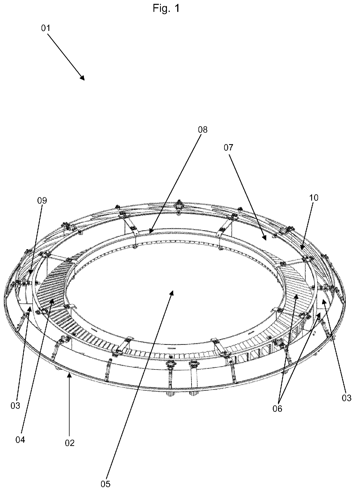
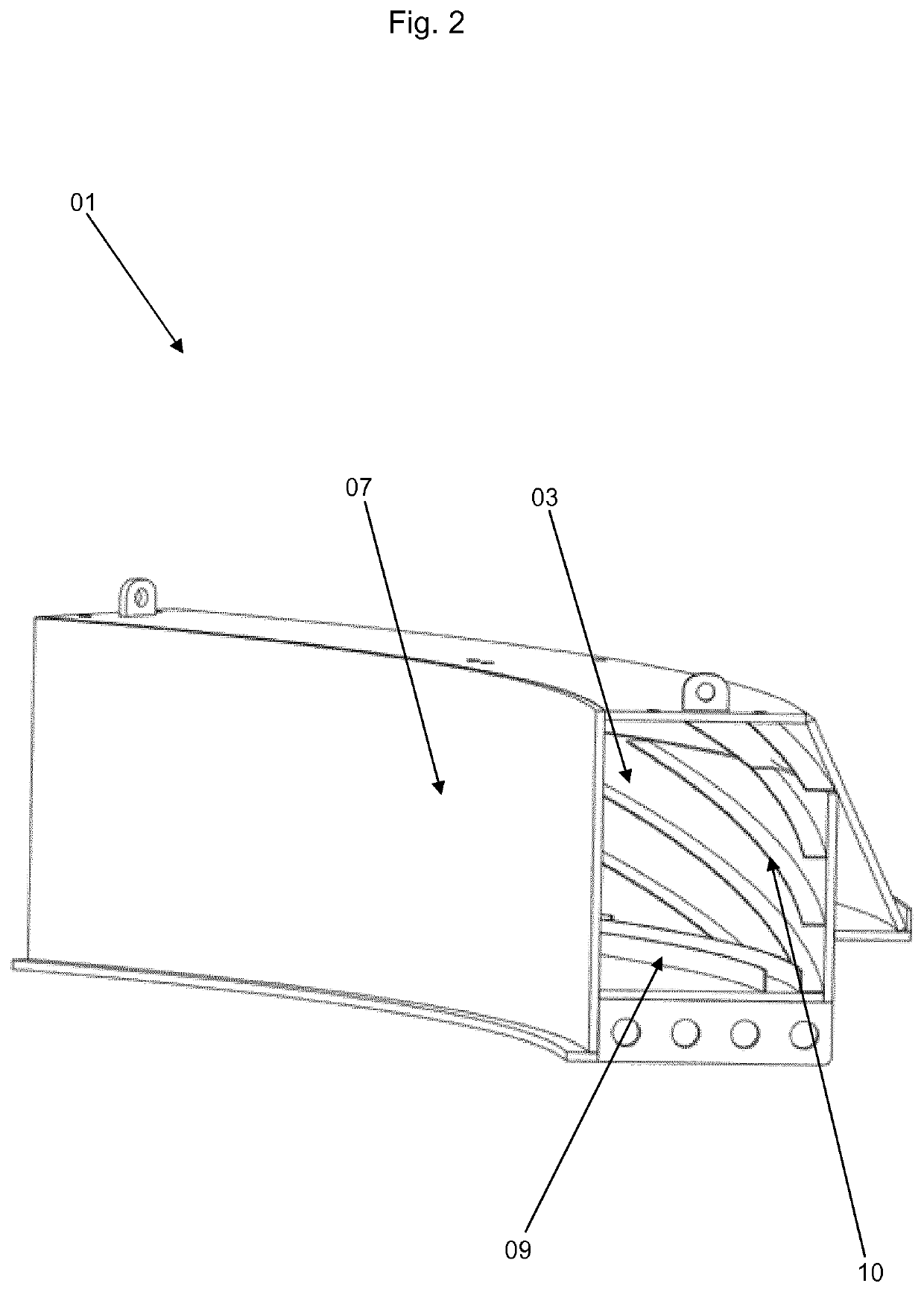
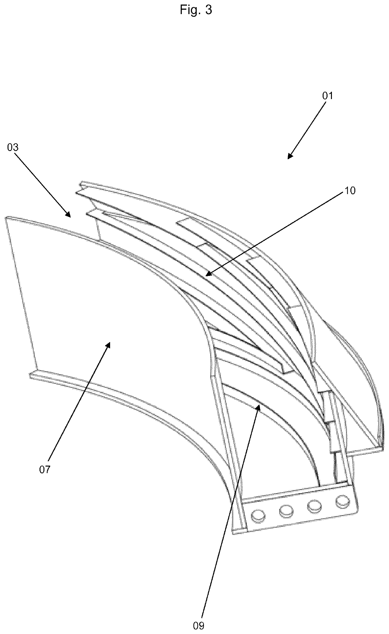
[0078]In a mixing device for a multiple-bed catalytic reactor, spirals (guide vanes and guide ramps) are arranged along the inside of the outer wall and floor of the mixing section of the mixing device. 24 guide ramps along the outer wall and 12 guide vanes along the floor, all 25 mm of height are arranged in the mixing device.

[0079]The observations are:[0080]At the entrance to the mixing section channel, dispersion of the liquid phase of the fluid is observed due to a “messy” inlet flow.[0081]Further within the mixing section, the liquid soon starts to distribute both near the ceiling and near the floor of the mixing section.[0082]Towards the end of the mixing section, approximately 220° around the circle of the mixing section, again a good fraction of the liquid phase is distributed along the full cross sectional area of the mixing section, indicating good dispersion.[0083]Result: The fraction of liquid being trapped at 90-100% concentration has been reduced from 35.8% in a...


PUM

PropertyMeasurementUnit
Thicknessaaaaaaaaaa
Thicknessaaaaaaaaaa
Angleaaaaaaaaaa

Abstract

The present invention relates to multi-bed catalytic reactor with a cylindrical shape comprising a mixing device mounted between two catalyst beds in the reactor, said mixing device has a circular outer rim which corresponds to the inner wall of the reactor, the mixing device comprises; collecting means disposed in a collecting section for collecting fluid from an up¬stream catalytic bed, mixing means disposed in a mixing section for mixing the collected fluid comprising guide vanes and guide ramps, and discharging means disposed in a discharging section for discharging the mixed fluid to a down-stream catalytic bed; wherein the collecting section, the mixing section and the discharging section are disposed outside the center of the circular cross-section of the reactor, as well as associated methods for mixing and the use of such a mixing device in catalytic reactors.

Description

FIELD OF THE INVENTION[0001]This invention relates to a reactor comprising a mixing device, specifically a multi-bed hydroprocessing reactor. Specifically, the mixing device is for use in down-flow catalytic reactors which include vertically superimposed packed beds of particulate catalytic material wherein a liquid, liquid and gas mixture or vapour is processed as it flows down through the packed beds. This type of reactor is used in the petroleum and chemical processing industries for carrying out various catalytic reactions, such as sulphur and nitrogen conversion (HDS / HDN); hydrogenation of: olefins (HYD) and aromatics (hydrodearomatisation—HDA), metals removal (hydrodemetallisation—HDM), oxygen conversion (hydrodeoxygenation—HDO) and hydrocracking (HC).BACKGROUND OF THE INVENTION[0002]Hydrocracking is a process for converting of heavy oil fractions to light oil fractions. Hydroprocessing is taking place in a hydroprocessing catalytic reactor which is the key element of a hydrop...

Claims


Application Information

Patent Timeline
IPC IPC(8): B01F3/04B01F5/00B01J8/04C10G45/44C10G45/32C10G47/00C10G49/00
CPCB01J8/0492B01F2215/0036C10G2300/207C10G45/32C10G45/44B01F3/04503B01F5/0057C10G2300/205C10G47/00B01J2208/00849C10G49/002C10G2300/202B01J8/0453B01J2208/00938B01J8/04B01F23/2323B01F25/10B01F2101/2204
Inventor HOLM-CHRISTENSEN, OLAVMANOHARAN, KARTHIK GOPALRISBJERG JARLKOV, KLAUSBRIX, JACOB
Owner HALDOR TOPSOE AS
Why Eureka
Try Eureka