Display apparatus

Active Publication Date: 2020-02-06
CORETRONIC
View PDF3 Cites 3 Cited by
  • Summary
  • Abstract
  • Description
  • Claims
  • Application Information

AI Technical Summary

Benefits of technology

[0006]The invention provides a display apparatus, which is convenie

Problems solved by technology

However, the double-sided bonding tape has limited an adhesive force.
However, a larger area necessarily occupies more space, which is not condu

Method used


Image

  • Display apparatus
  • Display apparatus
  • Display apparatus

Examples


Embodiment Construction

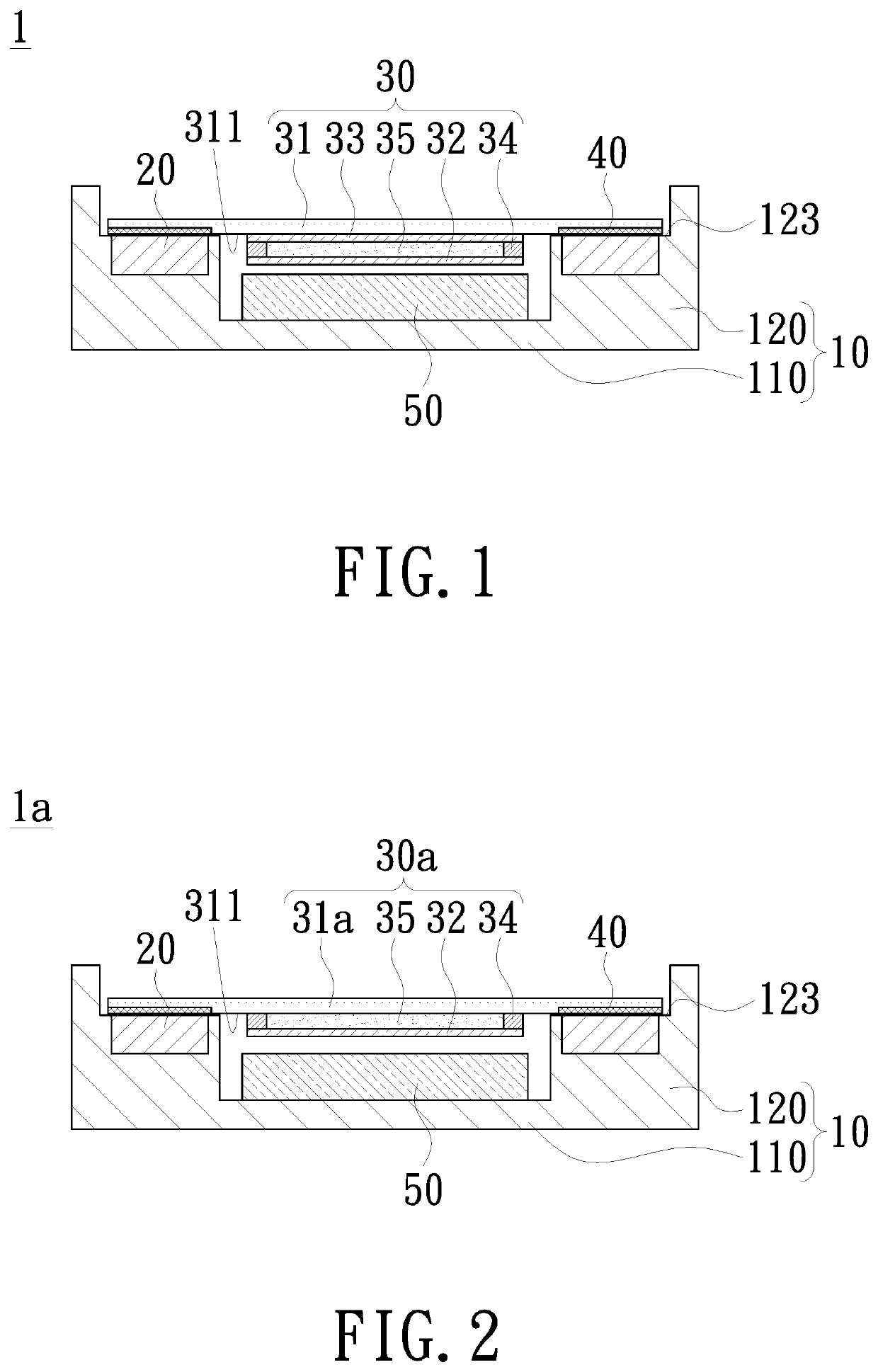
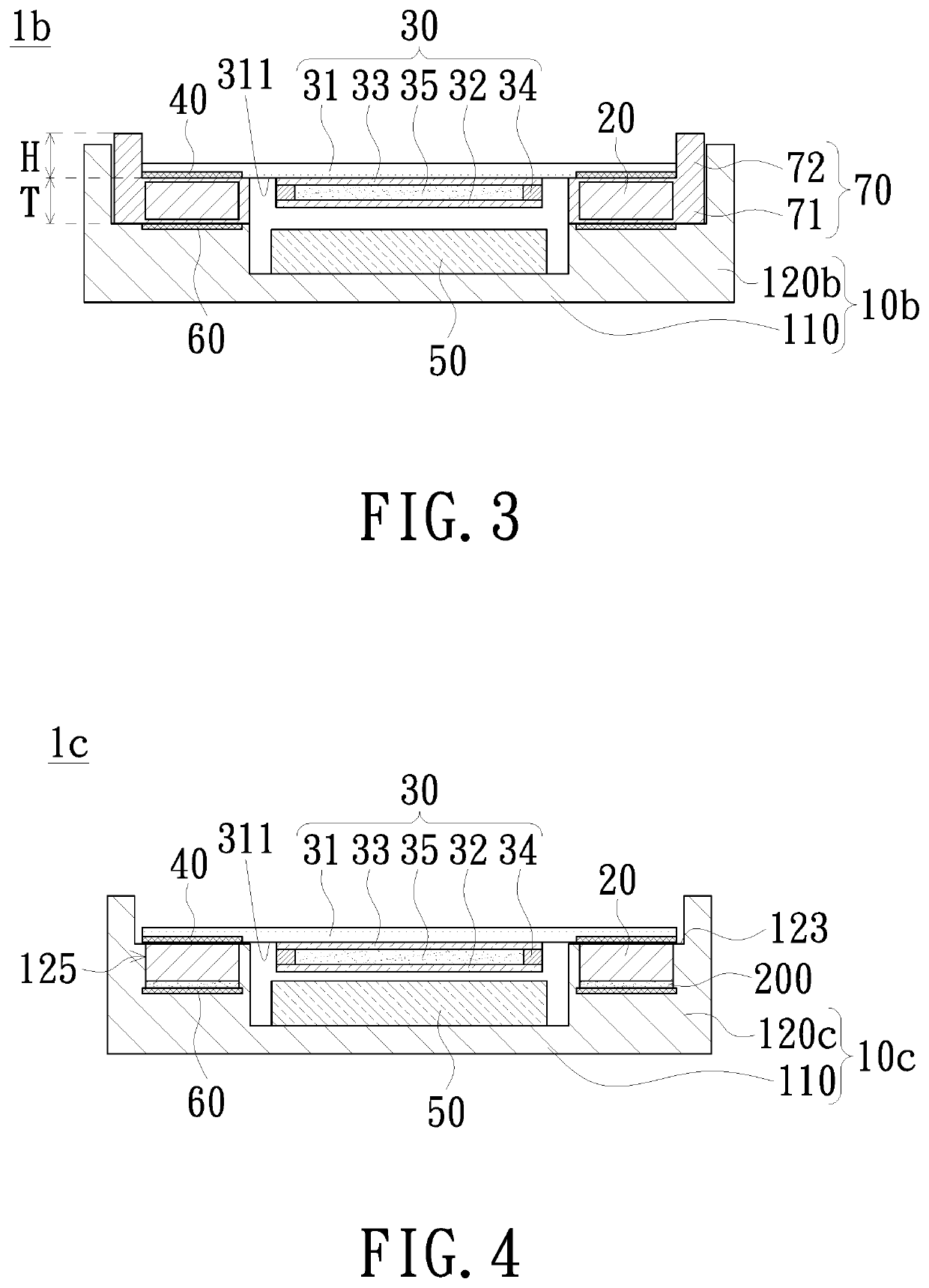
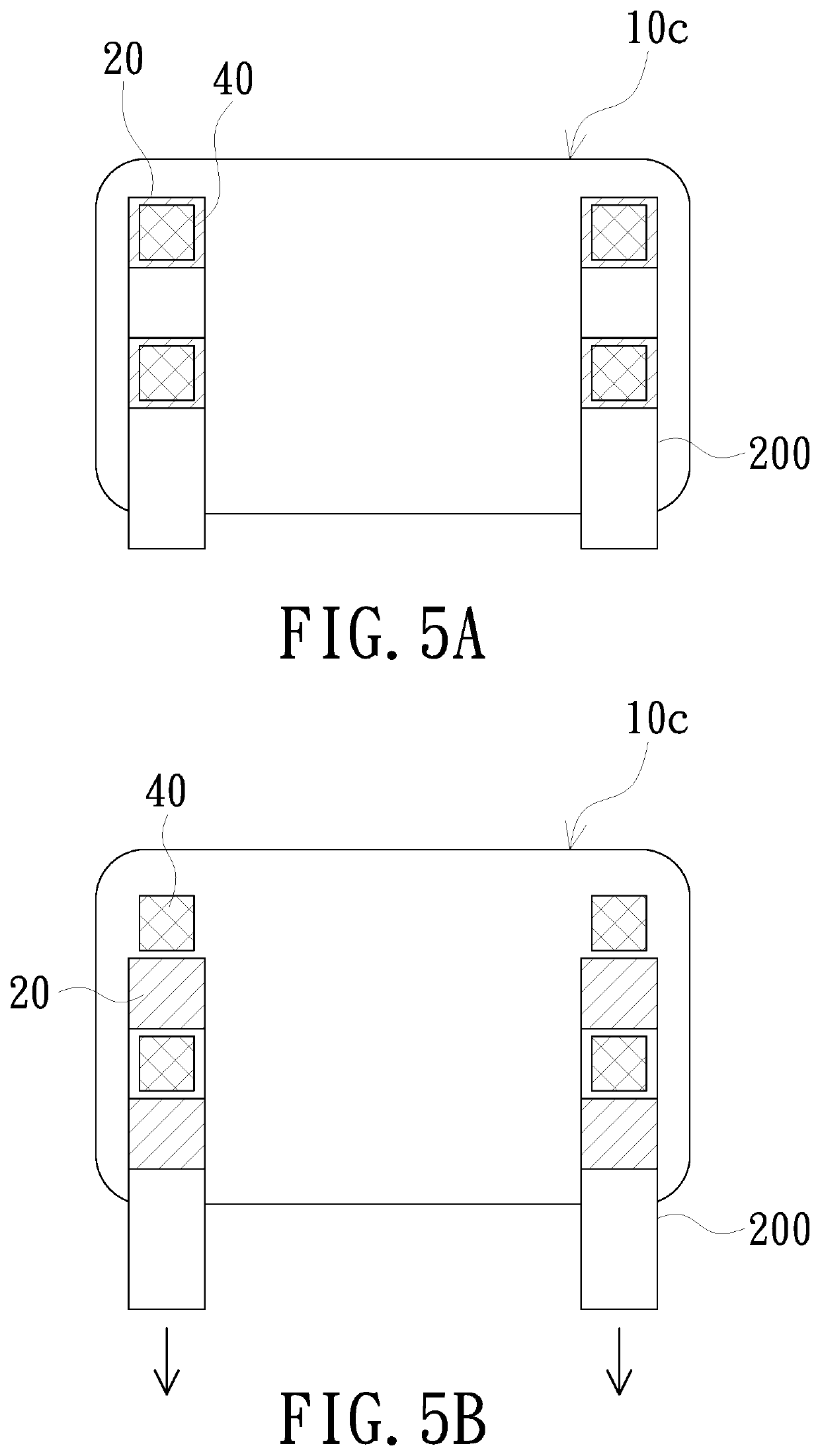
[0018]In the following detailed description of the preferred embodiments, reference is made to the accompanying drawings which form a part hereof, and in which is shown by way of illustration specific embodiments in which the invention may be practiced. In this regard, directional terminology, such as “top”, “bottom”, “front”, “back”, etc., is used with reference to the orientation of the Figure(s) being described. The components of the invention can be positioned in a number of different orientations. As such, the directional terminology is used for purposes of illustration and is in no way limiting. On the other hand, the drawings are only schematic and the sizes of components may be exaggerated for clarity. It is to be understood that other embodiments may be utilized and structural changes may be made without departing from the scope of the invention. Also, it is to be understood that the phraseology and terminology used herein are for the purpose of description and should not b...


PUM


Abstract

A display apparatus includes a back plate, a plurality of first magnetic components, a display module and second magnetic components. The back plate has a bottom wall and a carrying portion. The carrying portion is connected to the bottom wall and located at a periphery of the bottom wall. A plurality of first magnetic components is disposed on the carrying portion. The display module includes a first substrate. The carrying portion supports an edge of the first substrate. The second magnetic components are disposed to the edge of the first substrate and disposed oppositely to the first magnetic components respectively. The first magnetic components and the second magnetic components are coupled to each other by a magnetic force.

Description

CROSS-REFERENCE TO RELATED APPLICATION[0001]THIS APPLICATION CLAIMS THE PRIORITY BENEFIT OF CHINA APPLICATION (CN201810857108.0), FILED ON 2018 Jul. 7, 31. THE ENTIRETY OF THE ABOVE-MENTIONED PATENT APPLICATION IS HEREBY INCORPORATED BY REFERENCE HEREIN AND MADE A PART OF THIS SPECIFICATION.FIELD OF THE INVENTION[0002]The invention relates to a display apparatus, and more particularly to a fixing structure for a display module.BACKGROUND OF THE INVENTION[0003]Portable smart electronic products are necessities for modern people's lives. No matter consumers or entrepreneurs, in addition to essential functions, the requirements for lightness, thinness, power-saving, strength, and even product appearance of electronic products are getting higher and higher. There is a further requirement for visual taste on portable display apparatuses. In addition to a use of lightweight and sturdy materials, entrepreneurs also develop and design on an assembly structure.[0004]A display apparatus inclu...

Claims


Application Information

Patent Timeline
IPC IPC(8): G02F1/1333
CPCG02F1/133308G02F2001/133331G02F2001/133314G02F1/13338G02F2201/46G09F9/00G02F1/1333G02F1/133314G02F1/133331
Inventor HSU, JENG-BIN
Owner CORETRONIC
Why Eureka
Try Eureka