Supercharge Your Innovation With Domain-Expert AI Agents!

Projector and method of controlling projector

Active Publication Date: 2020-02-06
SEIKO EPSON CORP
View PDF0 Cites 0 Cited by
  • Summary
  • Abstract
  • Description
  • Claims
  • Application Information

AI Technical Summary

Benefits of technology

The present invention aims to solve the issue of burn-in on display devices without increasing their cost. The technical effect is to provide a cost-effective solution for resolving burn-in issues on display devices.

Problems solved by technology

However, the technology disclosed in Document 1 requires to be provided with a liquid crystal panel large in display area in order to keep the non-display area, and therefore incurs an increase in cost.

Method used


Image

  • Projector and method of controlling projector
  • Projector and method of controlling projector
  • Projector and method of controlling projector

Examples


modified example

[0115]Then, a modified example will be described.

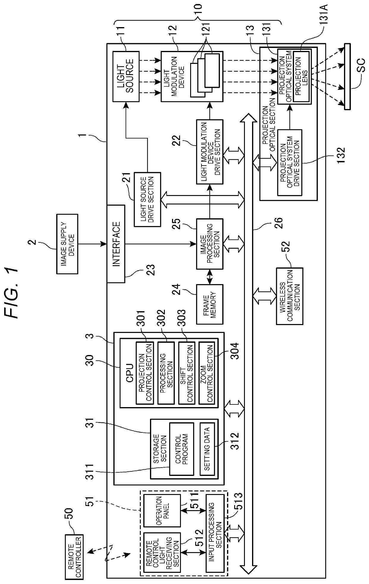
[0116]FIG. 8 is a block diagram showing a configuration of a projector 1 according to the modified example.

[0117]In the description of FIG. 8, substantially the same constituents as the constituents of the projector 1 shown in FIG. 1 are denoted by the same reference numerals, and the detailed description thereof will be omitted.

[0118]As is obvious from the comparison between FIG. 1 and FIG. 8, in the projector 1 according to the modified example, the control section 3 further functions as a calculation section 305.

[0119]When the projection lens 131A is shifted while the image processing section 25 is performing a keystone distortion correction on the projection image TG, the calculation section 305 calculates parameters related to the keystone distortion correction in accordance with the shift of the projection lens 131A. As the parameters related to the keystone distortion correction, a conversion parameter for performing the conver...


PUM


Abstract

A projector includes a projection section having a light source, a light modulation device and a projection lens, and modulating light emitted from the light source with the light device, and then projecting the light modulated through the projection lens to project a projection image on a screen, a projection optical system drive section for changing a projection position of the projection image, a projection control section for making the light device display a reduced input image, and a shift control section for controlling the projection optical system drive section wherein the projection position of the projection image when displaying the reduced input image at a central display position and at a shift display position become the same when the projection control section changes the display position of the reduced input image from the central display position to the shift display position in a display area of the light device.

Description

[0001]The present application is based on, and claims priority from JP Application Serial Number 2018-143264, filed Jul. 31, 2018, the disclosure of which is hereby incorporated by reference herein in its entirety.BACKGROUND1. Technical Field[0002]The present disclosure relates to a projector, and a method of controlling a projector.2. Related Art[0003]In the past, there has been known a technology of resolving burn-in occurring in a device for displaying an image (see, e.g., JP-A-2017-53953 (Document 1)). Document 1 discloses a technology of shifting an image displayed in a display area of a liquid crystal panel to a non-display area to move a projection position of a projection image toward an opposite direction to the shift direction of the image using a lens shift function of an optical system to thereby resolving the burn-in of the liquid crystal panel while preventing the shift of the projection position.[0004]However, the technology disclosed in Document 1 requires to be prov...

Claims


Application Information

Patent Timeline
IPC IPC(8): H04N9/31G03B21/14
CPCH04N9/3185G03B21/142G03B21/006H04N9/3188H04N9/3105G03B43/00
Inventor TSUKAGOSHI, SHINICHI
Owner SEIKO EPSON CORP
Features
  • R&D
  • Intellectual Property
  • Life Sciences
  • Materials
  • Tech Scout
  • Unparalleled Data Quality
  • Higher Quality Content
  • 60% Fewer Hallucinations
Learn More