Suction pad

a technology of suction pad and suction head, which is applied in the field of suction pad, can solve the problems of suction defect and suction power drop, and achieve the effect of preventing the leakage of negative pressure fluid to the exterior

Active Publication Date: 2020-02-13
SMC CORP
View PDF6 Cites 6 Cited by
  • Summary
  • Abstract
  • Description
  • Claims
  • Application Information

AI Technical Summary

Benefits of technology

[0014]In addition, for example, when a bag-shaped workpiece in which fluid contents are contained is attracted under suction and transported by the suction pad, even in the case that the shape of the workpiece changes due to movement of the contents or under the influence of gravity or the like, the suction pad is deformed in a manner so as to follow the shape of the workpiece, and by the first rib portions and the second rib portions being kept in abutment with the workpiece accompanying such deformation, the supply paths are surrounded by the first and second rib portions, and the negative pressure fluid can suitably be maintained in the interior of the supply paths. Further, since the supply paths of the negative pressure fluid are configured in a non-linear shape by the first and second rib portions in radial directions of the suction pad, leakage of the negative pressure fluid to the exterior can be prevented, in comparison with the suction pad according to the conventional art.

Problems solved by technology

However, with the suction pad discussed above, when the workpiece is deformed due to flowing of the contents therein or the like at the time that the workpiece is attracted under suction, the negative pressure fluid, which is supplied to the outer circumferential side of the skirt member between the convex surface portions and flows between the rib portions, flows in a linear manner toward the outer circumferential side, and there is a concern that the negative pressure fluid may leak to the exterior from the outer circumferential sides of opened rib portions, thus leading to a decrease in suction power and bringing about a suction defect.

Method used


Image

  • Suction pad
  • Suction pad
  • Suction pad

Examples


Embodiment Construction

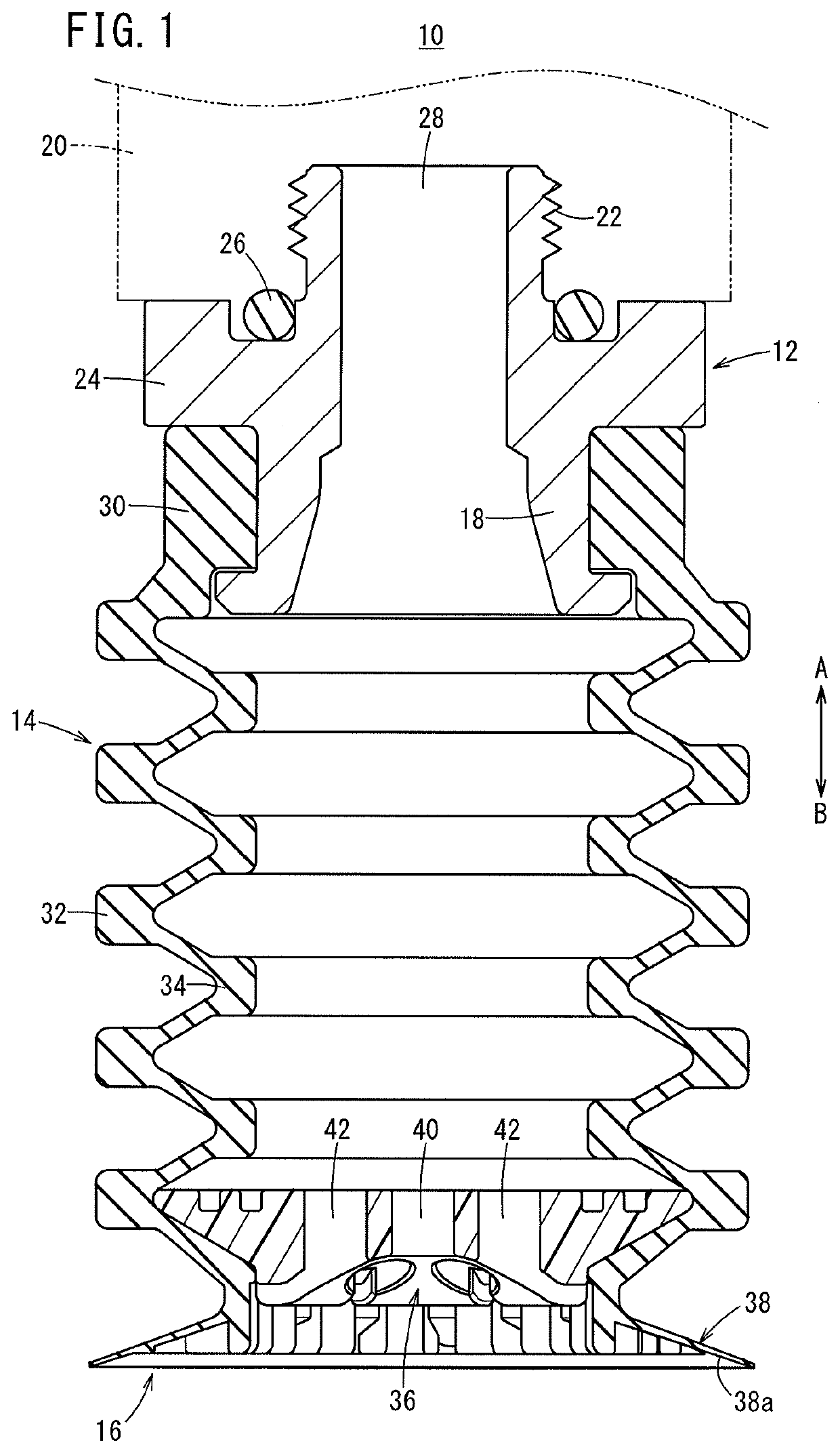
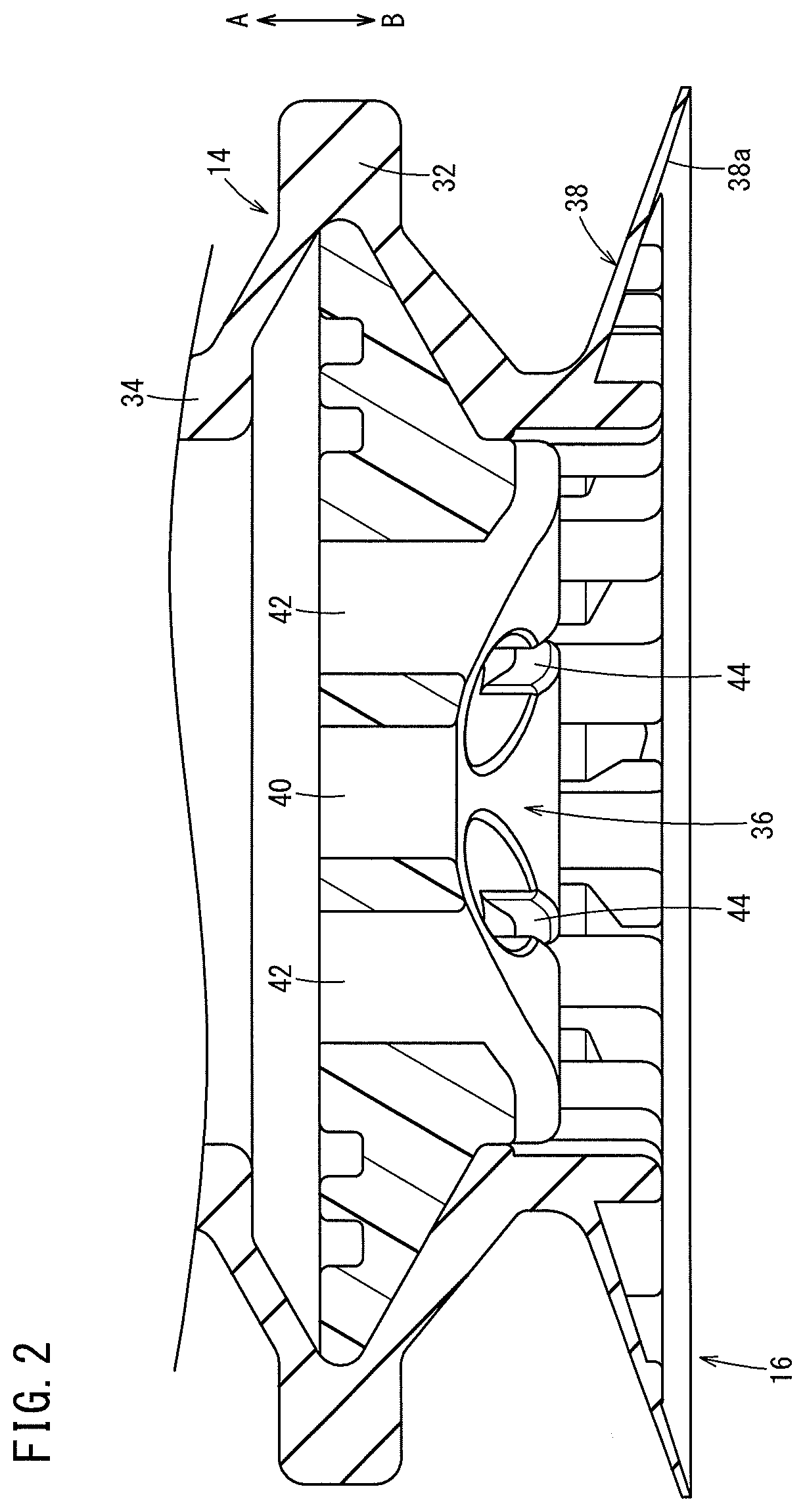
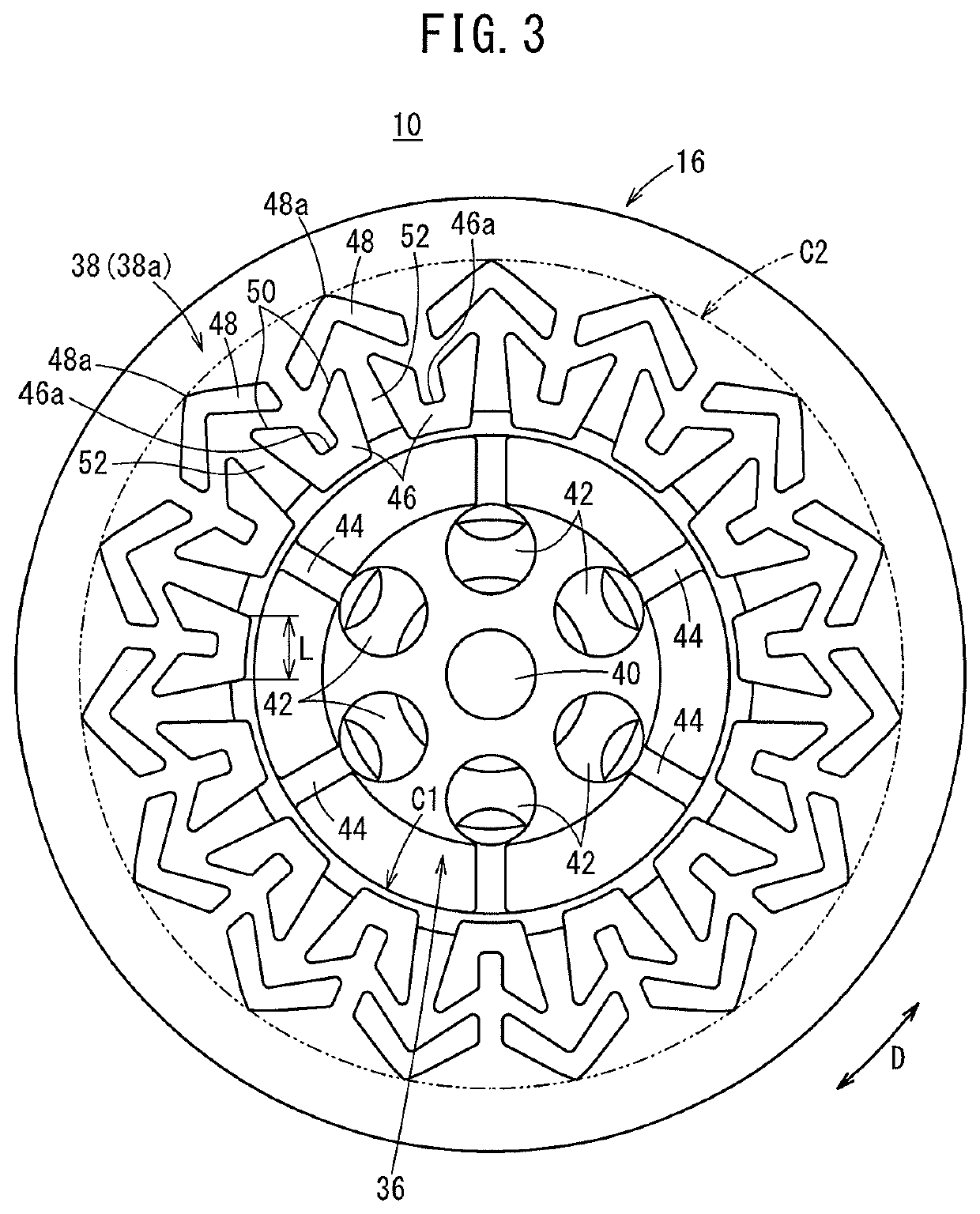
[0028]As shown in FIGS. 1 to 4, the suction device 10 includes an adapter (body) 12 connected through a tube to a non-illustrated negative pressure supply device, a bellows (bellows portion) 14 connected to a lower end of the adapter 12, and a pad member (suction member) 16 formed at the distal end (lower end) of the bellows 14.

[0029]The adapter 12 is formed, for example, in a cylindrical shape from a metal material, and on a lower end thereof, a connecting part 18 is formed to which the bellows 14 is connected, whereas on an upper end thereof, a threaded portion 22 is formed to which a joint 20 is connected. Between the connecting part 18 and the threaded portion 22, a flange portion 24 is formed that projects in a direction perpendicular to the axial direction. In addition, a seal ring 26 is attached to the flange portion 24 via an annular groove on an end surface on the side of the threaded portion 22. Moreover, when the joint 20 is connected to the adapter 12, the joint 20 abuts...


PUM


Abstract

A suction device includes an adapter having a supply passage to which a negative pressure fluid is supplied, a bellows connected to a lower end of the adapter, and a pad member formed at the distal end of the bellows. The pad member has plural first and second ribs on a suction surface that attracts a workpiece under suction. The first ribs are disposed on an outer circumferential side of an attachment provided in the center of the pad member and extend toward the outer circumferential side. The second ribs are provided on an outer circumferential side of the first ribs, and are disposed in a circumferentially offset manner with respect to the first ribs. Additionally, between the respective first ribs which are disposed alongside one another in the circumferential direction of a skirt, supply paths are formed to which the negative pressure fluid is supplied from the attachment.

Description

CROSS-REFERENCE TO RELATED APPLICATION[0001]This application is based upon and claims the benefit of priority from Japanese Patent Application No. 2018-149076 filed on Aug. 8, 2018, the contents all of which are incorporated herein by reference.BACKGROUND OF THE INVENTIONField of the Invention[0002]The present invention relates to a suction pad used in a suction device capable of attracting under suction and transporting a workpiece under a supply action of a negative pressure fluid.Description of the Related Art[0003]Heretofore, a suction device has been known in which there is included a suction pad for attracting under suction and transporting a workpiece by a supplied negative pressure fluid. In such a suction device, in the case of transporting a workpiece which is formed from a film in a bag shape and is filled with fluid contents, when the contents move inside the workpiece and the workpiece becomes deformed, the suction pad cannot follow along with the deformation, and the s...

Claims


Application Information

Patent Timeline
Patent Type & Authority Applications(United States)
IPC IPC(8): B25J15/06B65G47/91
CPCB25J15/0683B65G47/91B25J15/0616B23Q7/04G03F7/70691B65G2201/0238
Inventor NAKAYAMA, TORUSUGIYAMA, TORUMIYAZAKI, NORIYUKISAITOH, MASARUGOTO, YUKIYA
Owner SMC CORP
Why Eureka
Try Eureka