Refrigerator
a technology for refrigerators and refrigerators, which is applied in the field of refrigerators, can solve the problems of affecting the insulation load and performance of the refrigerator, the built-in refrigerator may be more susceptible to heat dissipation than the general refrigerator, and the rear surface of the refrigerator may be affected by hot air discharged to the rear, so as to achieve the effect of improving the convenience of us
- Summary
- Abstract
- Description
- Claims
- Application Information
AI Technical Summary
Benefits of technology
Problems solved by technology
Method used
Image
Examples
first embodiment
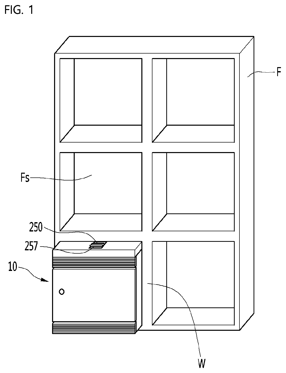
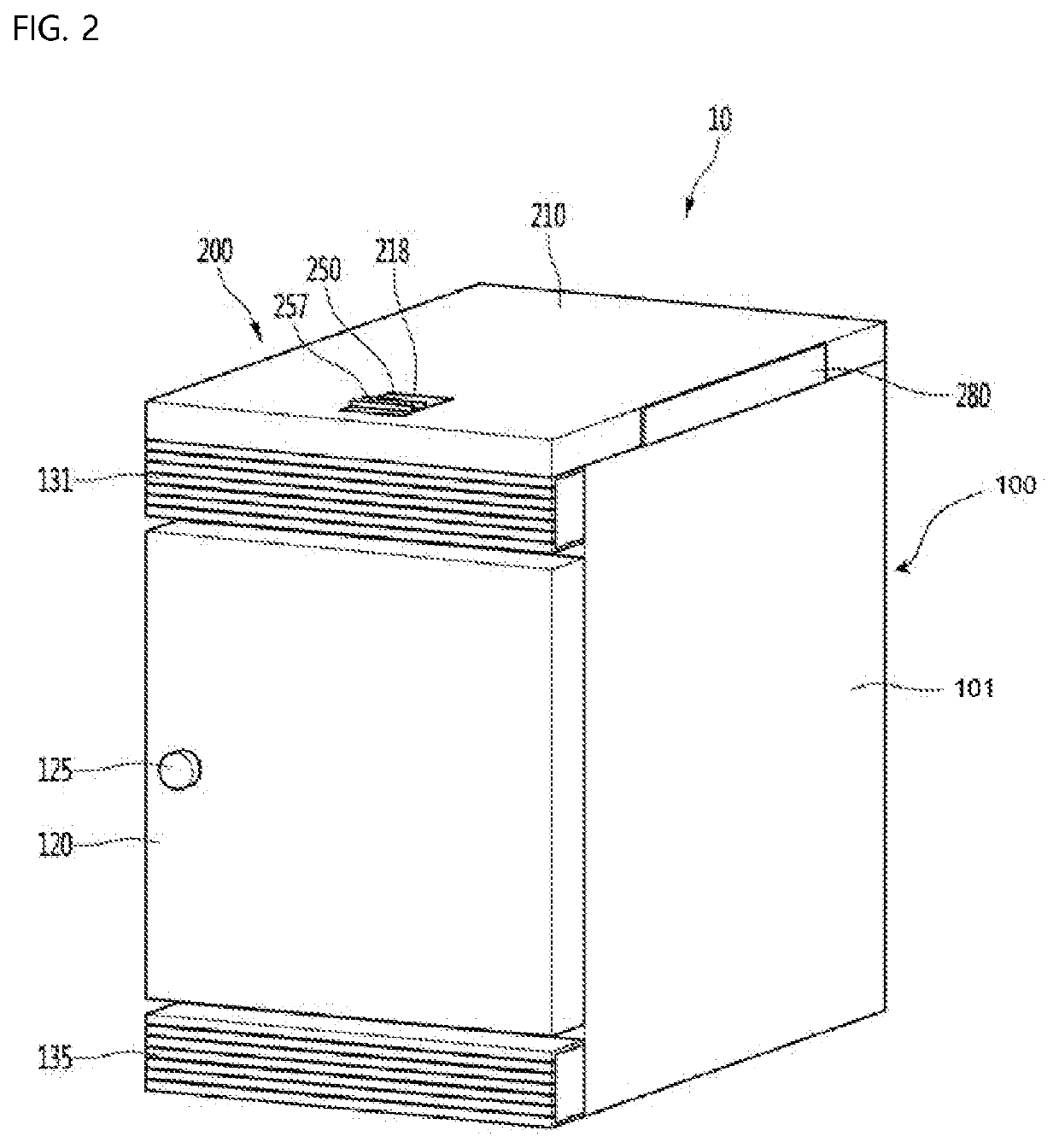
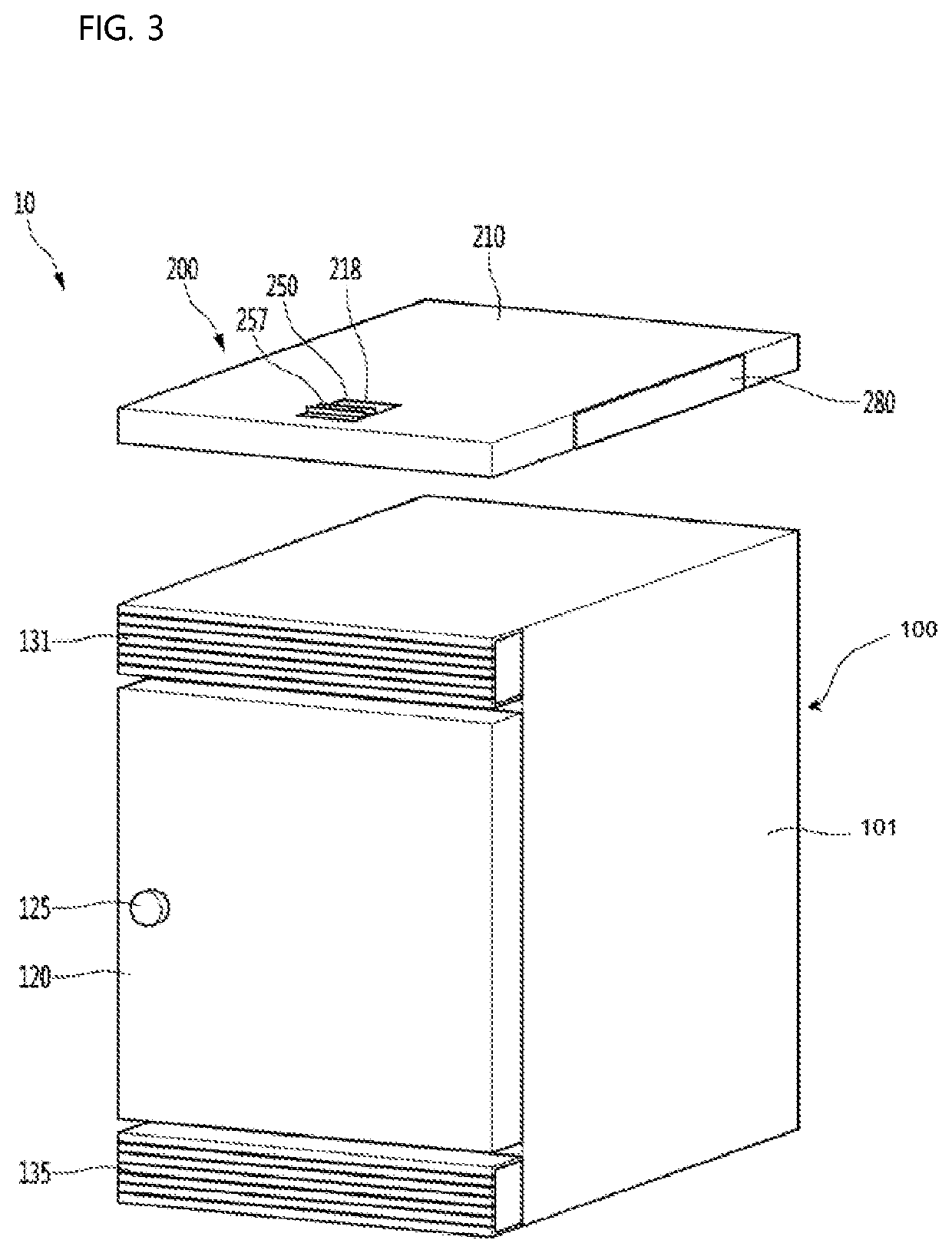
[0078]First, referring to FIG. 1, a refrigerator 10 according to the present invention may be housed in a storage space defined by a wall of an object to be installed. For example, the refrigerator 10 may be understood as a refrigerator which is installed by being embedded in a wall or furniture of a home or office. For example, FIG. 1 illustrates a state where the refrigerator 10 is installed in a storage space Fs formed in an object to be installed, in this case, a furniture F.
[0079]The refrigerator 10 may be installed by being fixed to the furniture F or may be detachably installed. In other words, the refrigerator 10 may be a portable refrigerator, and the refrigerator 10 may be normally used in a state of being inserted into the storage space Fs of the furniture F and may be taken out and used as an ice box by separating the refrigerator 10 from the furniture F when there is an event such as a picnic. When inserted, an outer surface of the refrigerator 10 may be positioned adja...
second embodiment
[0204]FIG. 20 is a view illustrating a configuration of a refrigerator according to the present invention.
[0205]Referring to FIG. 20, a refrigerator 10a according to a second embodiment of the present invention includes a contact mechanism 200a installed inside the outer case 101. In detail, the contact mechanism 200a may be positioned between the cabinet insulation material 105 which are disposed on the upper portion of the cabinet 100 and the outer case 101. Therefore, the outer case 101 may configure a housing which is provided in the contact mechanism 200a.
[0206]A lever 250a and an engaging member 257a provided on the upper portion of the contact mechanism 200a may protrude above the outer case 101. In addition, the description of the configuration of the contact mechanism 200a uses the description of the contact mechanism 200 according to the first embodiment.
[0207]According to this configuration, since the contact mechanism 200a is positioned inside the cabinet 100 of the ref...
third embodiment
[0208]FIGS. 21 and 22 are views illustrating a configuration and operation of a contact mechanism according to the present invention.
[0209]Referring to FIGS. 21 and 22, the frame 220 of the contact mechanism 200b according to the third embodiment of the present invention includes two lever supports 225 for supporting both sides of the guide plate 230. The two lever supports 225 are spaced apart from each other and the guide plate 230 may move between the two lever supports 225 in the front and rear direction. In other words, the lever support 225 functions as “a guide rail” of the guide plate 230.
[0210]The contact mechanism 200b may include a spring mechanism for providing the guide plate 230 with a restoring force. The spring mechanism includes a plate elastic member 271 coupled to a front portion of the guide plate 230. For example, the plate elastic member 271 may include a tension spring.
[0211]The plate elastic member 271 may be disposed between a spring coupling portion 255 and...
PUM
 Abstract
Description
Claims
Application Information
 - R&D
- Intellectual Property
- Life Sciences
- Materials
- Tech Scout
- Unparalleled Data Quality
- Higher Quality Content
- 60% Fewer Hallucinations
Browse by: Latest US Patents, China's latest patents, Technical Efficacy Thesaurus, Application Domain, Technology Topic, Popular Technical Reports.
© 2025 PatSnap. All rights reserved.Legal|Privacy policy|Modern Slavery Act Transparency Statement|Sitemap|About US| Contact US: help@patsnap.com


