Aircraft component plasma heaters

Inactive Publication Date: 2020-02-20
ROSEMOUNT AEROSPACE
View PDF0 Cites 1 Cited by
  • Summary
  • Abstract
  • Description
  • Claims
  • Application Information

AI Technical Summary

Benefits of technology

The patent is about a method to prevent ice from sticking to an airplane part. This is done by using a plasma heater to heat the part and make it too hot for ice to stick to. This can be combined with other methods to make the process more effective.

Problems solved by technology

However, such resistance based electric heaters may not be able to perform as desired.

Method used


Image

  • Aircraft component plasma heaters
  • Aircraft component plasma heaters

Examples


Embodiment Construction

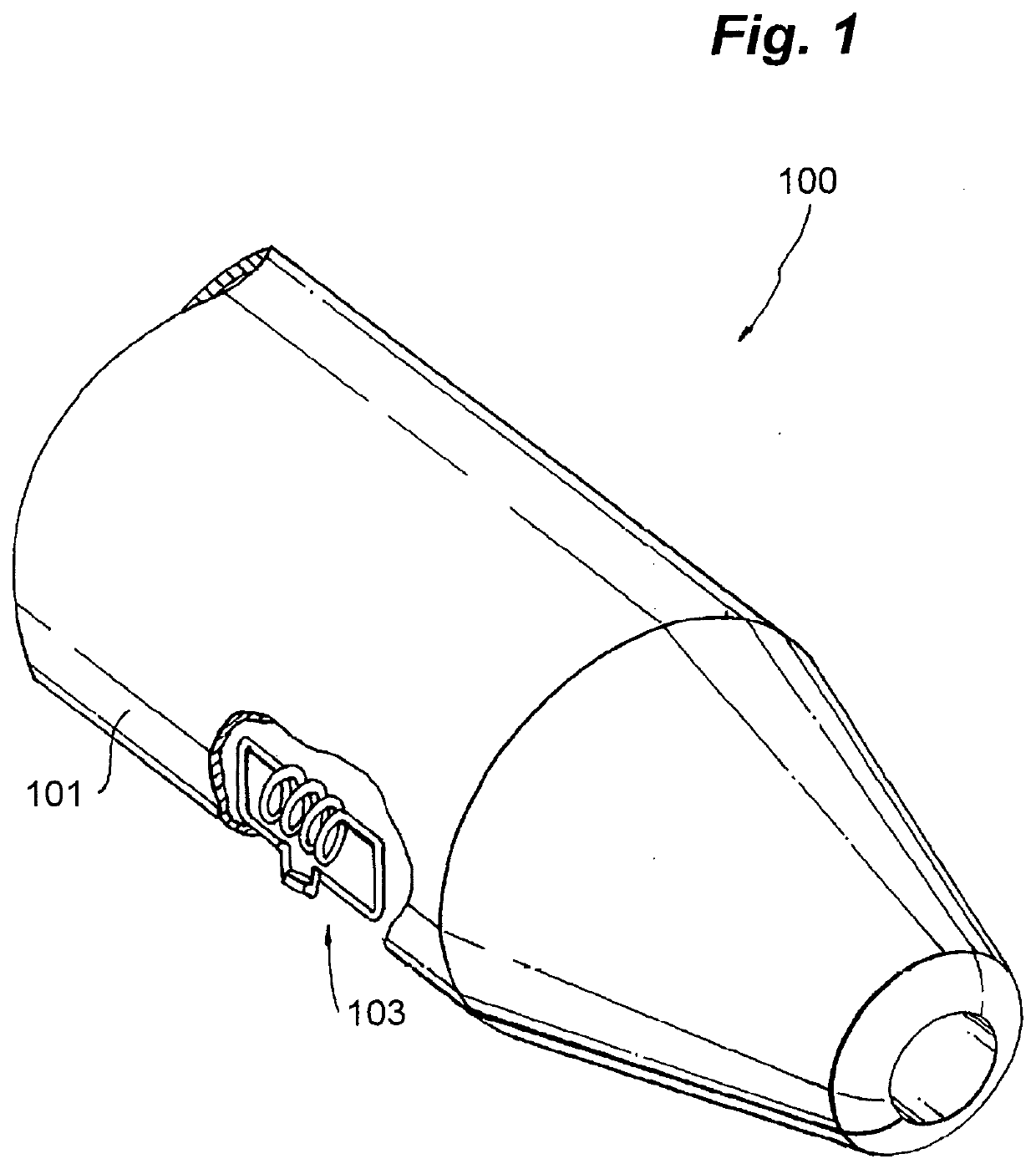
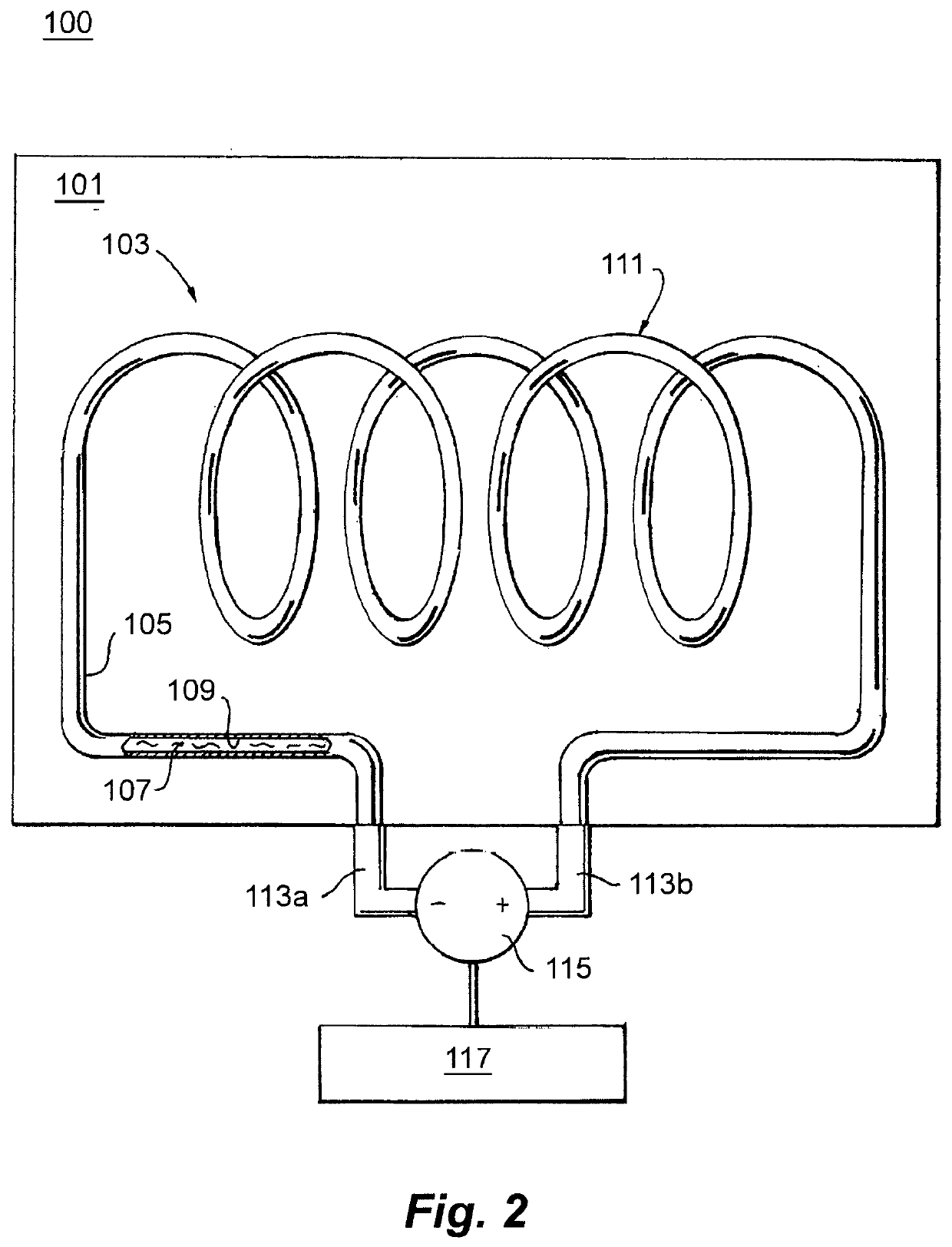
[0015]Reference will now be made to the drawings wherein like reference numerals identify similar structural features or aspects of the subject disclosure. For purposes of explanation and illustration, and not limitation, an illustrative view of an embodiment of an aircraft component in accordance with the disclosure is shown in FIG. 1 and is designated generally by reference character 100. Other embodiments and / or aspects of this disclosure are shown in FIG. 2.

[0016]Referring to FIG. 1, an aircraft component (e.g., an air data probe) 100 can include an aircraft component body 101 and a plasma heater 103 disposed at least partially on or at least partially within the component body 101 and configured to selectively heat the component body 101. The aircraft component 100 can be an air data sensor (e.g., a pitot tube as shown), and the aircraft component body 101 can be a sensor body. For example, the component body 101 can be a pitot tube, e.g., as shown in FIG. 1, for example. The a...


PUM


Abstract

An aircraft component can include an aircraft component body, and a plasma heater disposed at least partially on or at least partially within the component body and configured to selectively heat the component body. The aircraft component can be an air data sensor, and the aircraft component body can be a sensor body. The aircraft component can be any other suitable aircraft component (e.g., a portion of the airframe and / or any other suitable type of sensor and / or traditionally heated component).

Description

BACKGROUND1. Field[0001]The present disclosure relates to aircraft component heaters, e.g., air data sensor heaters.2. Description of Related Art[0002]Air data sensor probes, e.g., pitot probes, are used in flight operations of an aircraft. In such air data sensor probes, it is necessary to keep their plumbing and pneumatic tubes free of ice in order for the sensor to perform as expected. At the extremely cold temperatures in which the probes operate as an aircraft flies at high altitudes, a resistance based electric heater is traditionally used to ensure that such probes are deiced and continue to operate properly. However, such resistance based electric heaters may not be able to perform as desired.[0003]Such conventional methods and systems have generally been considered satisfactory for their intended purpose. However, there is still a need in the art for improved aircraft air data sensor heaters that provide the reliability required in such challenging environment. The present ...

Claims


Application Information

Patent Timeline
IPC IPC(8): H05H1/24G05B15/02H01J17/04H01J17/34B64D43/02
CPCH01J17/34H01J17/04G05B15/02H05H1/24B64D43/02B64D15/12B64D15/04H01J37/32
Inventor ESSAWY, MAGDI A.RAMTHUN, KENT A.
Owner ROSEMOUNT AEROSPACE
Why Eureka
Try Eureka