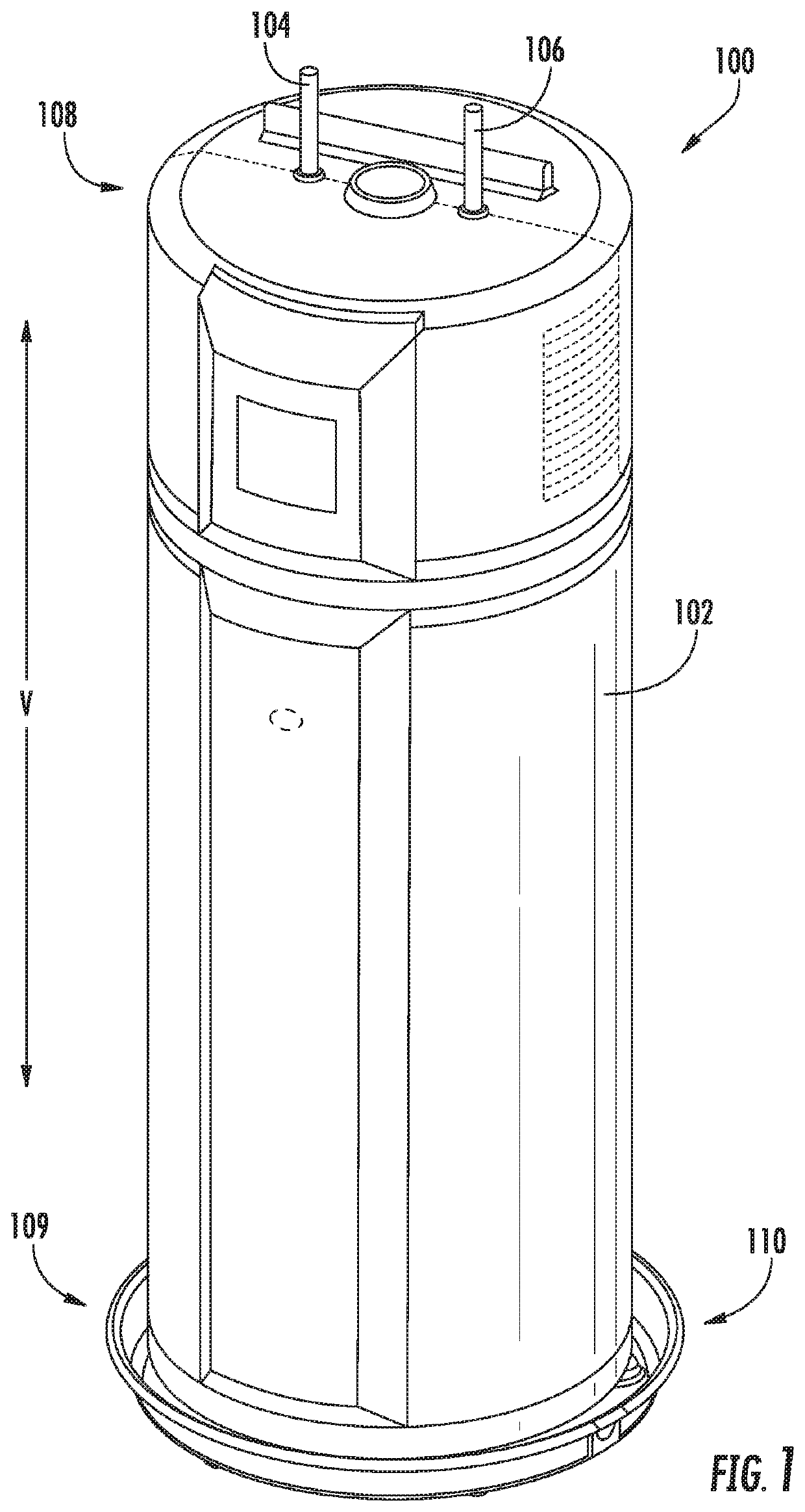
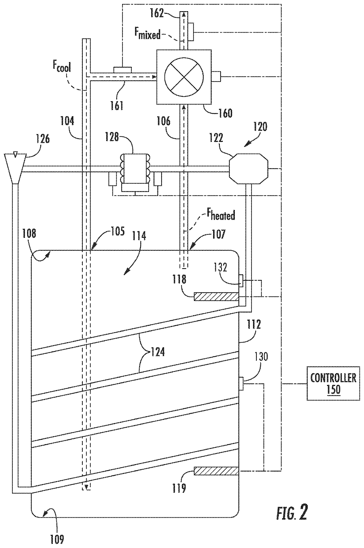
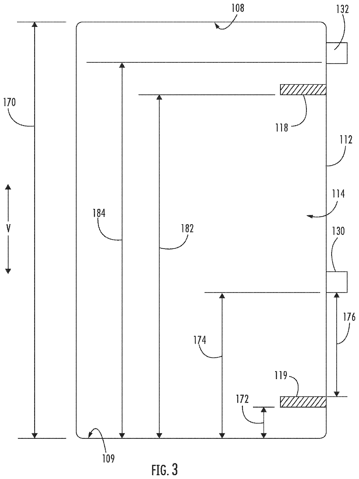
Electric hot water heater having a separated temperature sensor and heating element

Active Publication Date: 2020-02-27
HAIER US APPLIANCE SOLUTIONS INC
View PDF8 Cites 0 Cited by
  • Summary
  • Abstract
  • Description
  • Claims
  • Application Information

AI Technical Summary

Benefits of technology

The electric water heater appliance described in this patent has a tank with an electric heating element and a temperature sensor. The temperature sensor is attached to the tank and there is a gap between the electric heating element and the temperature sensor. The ratio of the gap to the volume of the tank is defined as equal to or greater than 0.1. This design helps to improve the efficiency of the electric water heater appliance.

Problems solved by technology

Thus, the volume of heated water available at the predetermined temperature is generally limited to the volume of the tank.
Although the close proximity between the heating element and the electromechanical temperature sensor may facilitate easy installation of the heating element and electromechanical temperature sensor, the design also presents a number of drawbacks.
For instance, the water heater appliance may be especially prone to temperature stacking within the tank.
Relatively small water draws, such as those caused by hand washing, may cause water adjacent to the electromechanical temperature sensor and heating element to fall below the predetermined temperature threshold, thereby leading to activation of the heating element, even though most of the water within the tank may be above the predetermined temperature threshold.
Oftentimes, this causes the heating element to overheat the water above the desired temperature, especially if the heating element is a relatively high power heating element, which quickly heats water within the water heater tank.
Having this hot water slug may then lead to high and variable hot water temperatures above the set temperature being supplied by the water heater appliance during a subsequent water draw.
Along with affecting variation of hot water temperatures from the water heater appliance, this may increase cycling of the heating elements, which may in turn decrease the reliability and useful life of the heating element.

Method used


Image

  • Electric hot water heater having a separated temperature sensor and heating element
  • Electric hot water heater having a separated temperature sensor and heating element
  • Electric hot water heater having a separated temperature sensor and heating element

Examples


Embodiment Construction

[0015]Reference now will be made in detail to embodiments of the invention, one or more examples of which are illustrated in the drawings. Each example is provided by way of explanation of the invention, not limitation of the invention. In fact, it will be apparent to those skilled in the art that various modifications and variations can be made in the present invention without departing from the scope or spirit of the invention. For instance, features illustrated or described as part of one embodiment can be used with another embodiment to yield a still further embodiment. Thus, it is intended that the present invention covers such modifications and variations as come within the scope of the appended claims and their equivalents.

[0016]The terms “includes” and “including” are intended to be inclusive in a manner similar to the term “comprising.” Similarly, the term “or” is generally intended to be inclusive (i.e., “A or B” is intended to mean “A or B or both”). The terms “first,”“se...


PUM


Abstract

An electric water heater appliance is provided herein. The electric water heater appliance may include a tank, an electric heating element, and a temperature sensor. The tank may define an interior volume extending from a top portion to a bottom portion. The interior volume may define a volume height along a vertical direction between the bottom portion and the top portion. The electric heating element may be operable to heat water within the interior volume. The temperature sensor may be attached to the tank above the electric heating element. A sensor gap may be defined along the vertical direction between the electric heating element and the temperature sensor.

Description

FIELD OF THE INVENTION[0001]The present subject matter relates generally to water heater appliances, and more particularly to water heater appliances having one or more electric heating elements or temperature sensors.BACKGROUND OF THE INVENTION[0002]Certain water heater appliances include a tank therein. Heating elements heat water within the tank during operation of such water heater appliances. In particular, the heating elements generally heat water within the tank to a predetermined temperature. The predetermined temperature is generally selected such that heated water within the tank is suitable for showering, hand washing, etc.[0003]During operation, relatively cool water flows into the tank, and the heating elements operate to heat such water to the predetermined temperature. Thus, the volume of heated water available at the predetermined temperature is generally limited to the volume of the tank. Accordingly, water heater appliances are sold in various sizes to permit consu...

Claims


Application Information

Patent Timeline
IPC IPC(8): F24H9/20F24H1/20F24H9/18
CPCF24H9/2021F24H1/201F24H9/1818F24H15/281F24H15/38F24H15/174F24H15/414F24H15/225F24H15/37
Inventor TSAI, CRAIG LUNG-PEICONSTANCE, ALAN GEORGE
Owner HAIER US APPLIANCE SOLUTIONS INC
Why Eureka
Try Eureka