Broom with integrated suction device

Inactive Publication Date: 2020-03-05
VALLILLO VINCENT A
View PDF0 Cites 2 Cited by
  • Summary
  • Abstract
  • Description
  • Claims
  • Application Information

AI Technical Summary

Benefits of technology

The patent describes a broom assembly with a handle and a broom head. The handle has an inner handle surface with a vacuum flow path defined by its inner handle surface and the inner intake surface of the handle. The broom head has a plurality of groups of bristles that are mounted at different sweep angles. The groups of bristles are positioned within mounting apertures in the base of the broom and the intake section has an inner intake surface with a vacuum flow path. The intake mouth is angled relative to the sweeping plane. The technical effects of this design include improved vacuum suction, improved bristle arrangement for sweeping, and a more efficient intake section for collecting bristles.

Problems solved by technology

This process must be repeated to adequately clean the surface, resulting in an inefficient process that places a significant physical burden on the user.
Prior art brooms that incorporate vacuums are overly complicated and difficult to use.
This places design constraints on the vacuum itself, undermining its efficacy, and adds significant weight to the head of the broom making it more difficult to use.
This additional step is inefficient and physically taxes the user.

Method used


Image

  • Broom with integrated suction device
  • Broom with integrated suction device
  • Broom with integrated suction device

Examples


Embodiment Construction

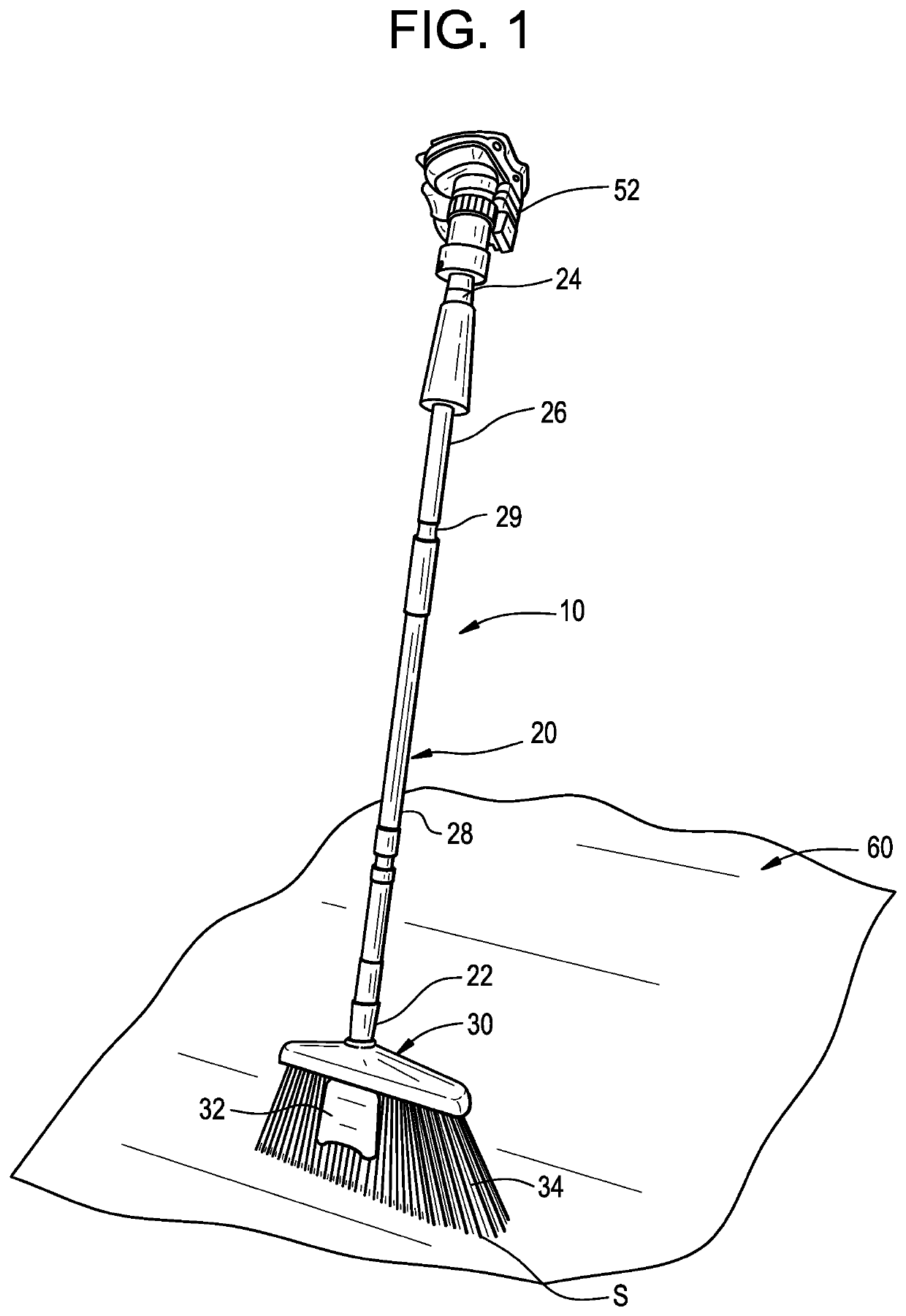
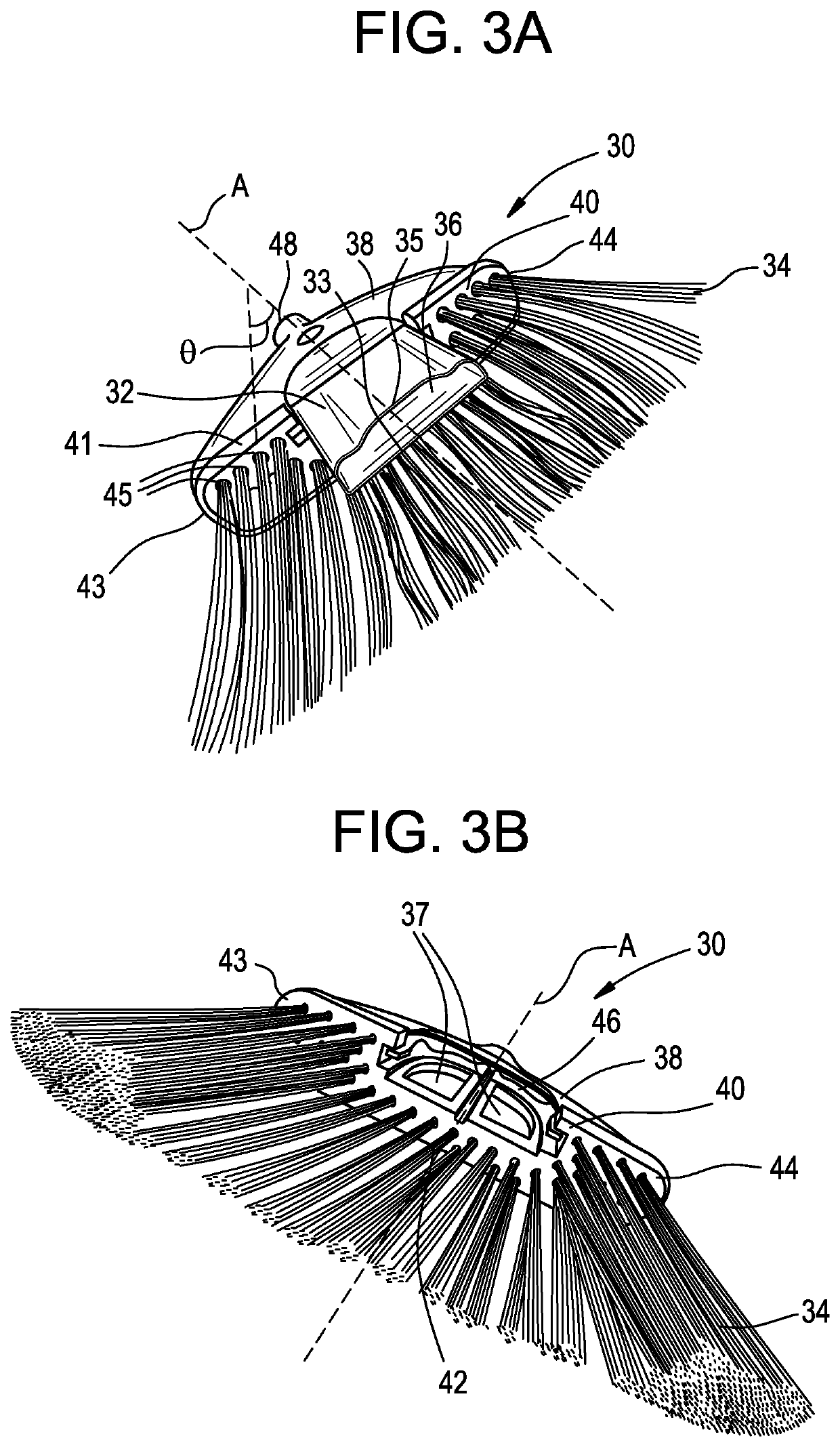
[0033]As shown in FIGS. 1-3B, 5A, and 5B, a broom assembly is generally designated by the numeral 10. The broom assembly 10 includes a broom head 30 secured to a handle 20 that extends from a first end 22 to a second end 24. The broom head 30 integrates an intake section 32 into a plurality of groups of bristles 34 mounted to the broom head 30. In other words, the intake section 32 takes the place of a plurality of groups of bristles 34 mounted to the broom head 30.

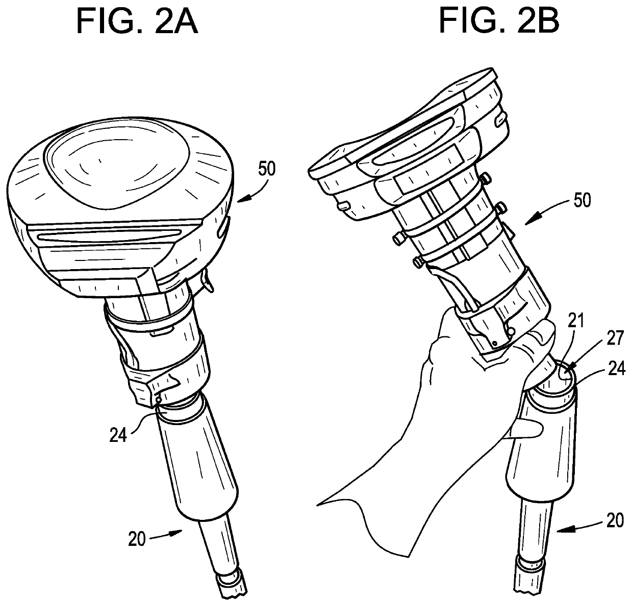
[0034]Referring to FIG. 1, the handle 20 extends from the first end 22, connected to the broom head 30 at a handle receiving aperture 48, to the second end 24. In the embodiment depicted in FIGS. 1-2B, the handle 20 has an inner surface 21 that defines a vacuum flow path. In the depicted embodiment, the handle 20 comprises a first handle section 26 and a second handle section 28 slidingly mounted to one another and joined at annular lock 29. The annular lock 29, the first handle section 26, and the second handle section 2...


PUM


Abstract

A broom assembly including a hollow handle extending from a broom head to a vacuum assembly and defining a vacuum flow path. The broom head has a base bottom and groups of bristles and a flexible intake section are mounted within the base bottom. A vacuum assembly is secured to the hollow handle at the end opposite the broom head and the vacuum assembly includes a suction motor and a removable container. A vacuum flow path from the intake section through the hollow handle is subject to suction forces by the suction motor and particulates swept together by the bristles travel through the vacuum flow path and collect in the container.

Description

FIELD OF THE INVENTION[0001]The present invention relates generally to a broom with an integrated suction device, and more specifically to a broom that incorporates an intake section of the suction device into the head of the broom.BACKGROUND OF THE INVENTION[0002]Brooms are used to sweep up loose materials. Typically, the user must sweep up the loose materials or debris using the broom and then use a separate device, such as a dustpan, to collect and remove the debris. This process must be repeated to adequately clean the surface, resulting in an inefficient process that places a significant physical burden on the user.[0003]Prior art brooms that incorporate vacuums are overly complicated and difficult to use. In one type of prior art broom, the entire vacuum is contained within the head of the broom. This places design constraints on the vacuum itself, undermining its efficacy, and adds significant weight to the head of the broom making it more difficult to use. In another type of...

Claims


Application Information

Patent Timeline
IPC IPC(8): A47L9/06A47L9/32
CPCA47L9/0606A47L9/322A46B15/0053A46B2200/302
Inventor VALLILLO, VINCENT A.
Owner VALLILLO VINCENT A
Why Eureka
Try Eureka