
Power Tool

Active Publication Date: 2020-03-05
BOSCH POWER TOOLS CHINA +1
View PDF0 Cites 5 Cited by
  • Summary
  • Abstract
  • Description
  • Claims
  • Application Information

AI Technical Summary

Benefits of technology

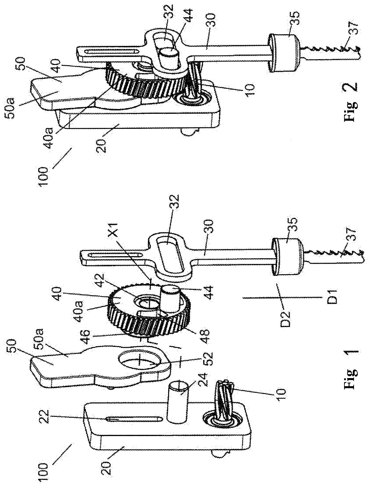
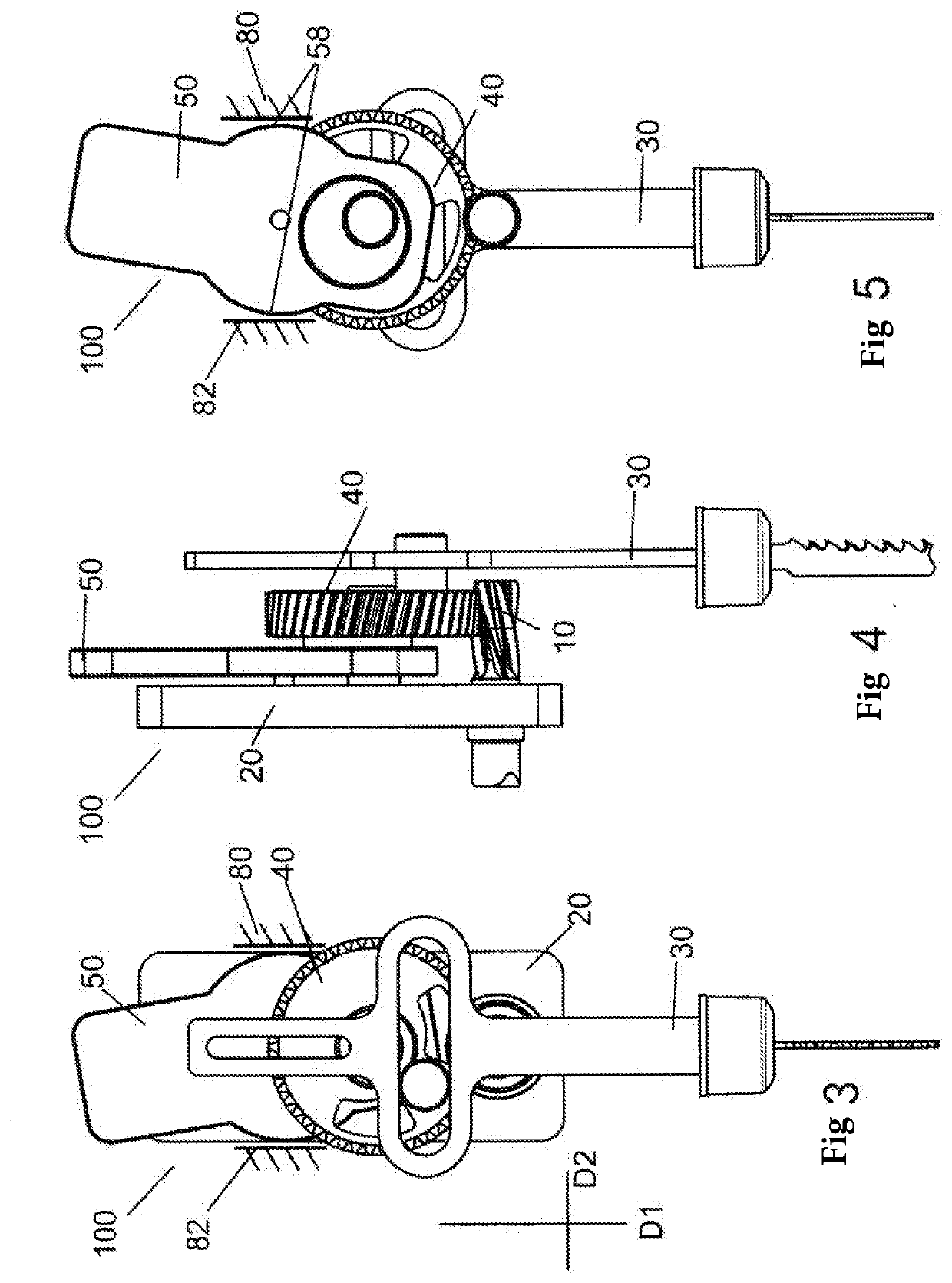
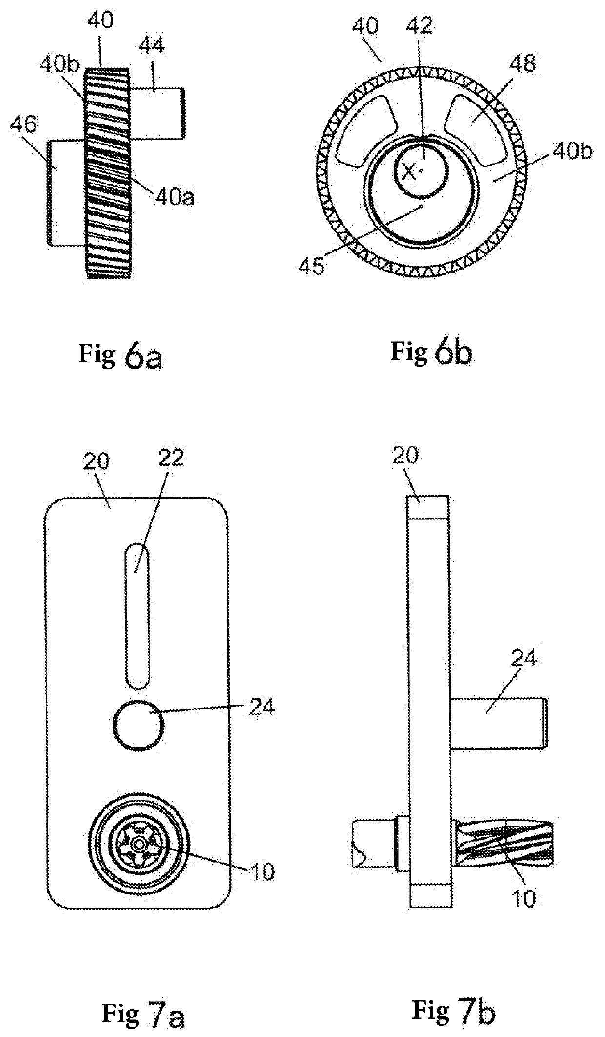
The present invention describes an electric tool with reduced vibration and improved stability. This is achieved through the use of a counterweight and an eccentric rotary wheel that work together to balance the inertial force generated by the movement of the tool. The counterweight and rotary wheel are designed to have opposite inertial force components in the perpendicular direction, which helps to cancel out vibration. This results in a more stable and comfortable tool operation, with reduced risk of damage to internal components.

Problems solved by technology

The action means frequently changing movement direction causes vibration in the electric tool due to the effect of inertia, thereby shortening the service life of the electric tool; it is also likely to result in the operator suffering physiological fatigue injury, and at the same time affects the comfort of the operator when operating the electric tool.
However, while balancing the inertial force of the action means in the vertical direction, this eccentric mass generates a force component in a horizontal direction perpendicular to the vertical movement direction, thereby triggering a vibration side effect again.

Method used


Image

  • Power Tool
  • Power Tool
  • Power Tool

Examples


Embodiment Construction

[0021]As used herein, the term “electric tool” includes but is not limited to reciprocating electric saws such as jigsaws, and electric hammers, etc. Portable electric tools of other types suitable for the principle of the present invention are also included in the scope of the present invention, which scope is not limited in any way to the detailed structures and forms shown in the figures and described here, but is defined only by the claims.

[0022]Overall, an electric tool according to the present invention comprises a drive means outputting rotational movement, an action means performing reciprocating linear movement in a linear movement direction, and a movement conversion mechanism converting rotational movement from a drive component to reciprocating linear movement of an output component. In order to avoid or minimize vibration of the electric tool caused by an inertial force of the action means performing reciprocating linear movement, the electric tool of the present invent...


PUM

PropertyMeasurementUnit
Forceaaaaaaaaaa
Massaaaaaaaaaa

Abstract

An electric tool includes a rotary wheel driven to rotate around a central axis thereof, an action member configured to bear a cutter of the electric tool, and a counterweight. The rotary wheel drives the action member such that it reciprocates linearly in a first direction. The rotary wheel simultaneously drives the counterweight such that it not only reciprocates linearly in the first direction in an opposite manner to the action member, but also performs reciprocating swinging movement in a plane perpendicular to the central axis. The first direction is parallel to the plane.

Description

TECHNICAL FIELD[0001]The present application relates to the field of electric tools, in particular to an electric tool outputting reciprocating linear movement.BACKGROUND ART[0002]Common electric tools, such as reciprocating saws and electric hammers, comprise a drive means outputting rotational movement, an action means outputting reciprocating linear movement, and a movement conversion mechanism converting rotational movement of the drive means to reciprocating linear movement of the action means.[0003]The action means of an electric tool of this type subjects a target workpiece to an operation such as reciprocating pounding or reciprocating cutting by performing reciprocating linear movement. When driven to perform reciprocating linear movement, the action means will change movement direction frequently. The action means frequently changing movement direction causes vibration in the electric tool due to the effect of inertia, thereby shortening the service life of the electric to...

Claims


Application Information

Patent Timeline
IPC IPC(8): B23D49/16
CPCB23D49/165B23D49/14B23D51/16B25D11/12B25D17/24B25D2217/0088B23D49/10
Inventor WANG, JIA
Owner BOSCH POWER TOOLS CHINA
Learn More