
A helical end mill

An end mill and spiral technology, applied in the field of spiral end mills, can solve the problems of reduced surface processing quality of parts, low machining efficiency, scrapped workpieces, etc., and achieve the effect of prolonging tool life, improving surface finish and eliminating vibration.

Inactive Publication Date: 2011-12-21
锑玛(苏州)精密工具股份有限公司
View PDF8 Cites 0 Cited by
  • Summary
  • Abstract
  • Description
  • Claims
  • Application Information

AI Technical Summary

Problems solved by technology

The helix angle of the traditional helical end mill is evenly distributed, so it has the following disadvantages: 1. The processing will generate continuous harmonic vibration, which will reduce the surface processing quality of the part, cause the workpiece to be repaired, and may even scrap the workpiece; 2. It cannot be used High feed cutting, low machining efficiency

Method used


Image

  • A helical end mill
  • A helical end mill
  • A helical end mill

Examples


Embodiment 1

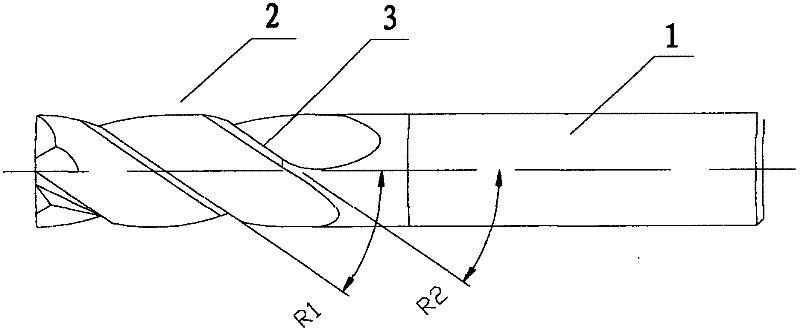
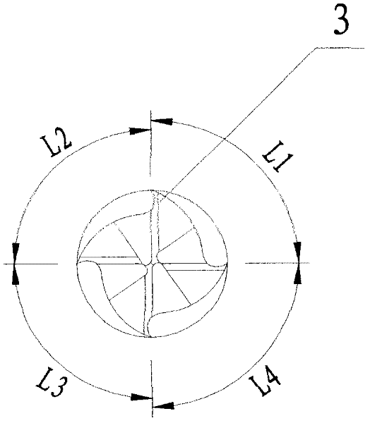
[0014] Such as figure 1 , 2 As shown, this embodiment is a four flute helical end mill with X-CEED coating on its surface. The four flute helical end mill includes a shank 1 and a blade 2. The blade 2 is provided with multiple For one parabolic side edge 3, the helix angles of the plurality of side edges 3 are different, and the distances between adjacent side edges in the plurality of side edges 3 are different.

[0015] Specifically:

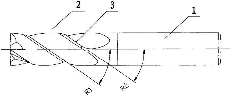
[0016] Such as figure 1 As shown, the helix angle R1 of some side cutting edges 3 is 41°, and the helix angle R2 of some side cutting edges 3 is 38°. By analogy, the helix angles of the four side cutting edges 3 are different, and the difference between the helix angles The difference is 3 degrees.

[0017] Such as figure 2 As shown, the distances L1, L2, L3, and L4 between adjacent side edges are represented by angles, and the specific values ​​are as follows: L1=84°, L2=87°, L3=93°, L4=96°, that is, adjacent side edges The pitches are...


PUM


Abstract

The purpose of the present invention is to propose a helical end mill that can reduce or eliminate harmonic vibration generated during processing, thereby improving processing quality and processing efficiency. The helical end mill of the present invention includes a shank and a cutting edge, and the cutting edge is provided with a plurality of parabolic side cutting edges along its own axial direction. The key point is that the helical angles of the plurality of side cutting edges are different. During the machining process, multiple side edges with different helix angles can generate a cutting motion of a different phase, thereby preventing the generation of resonance, thereby reducing or eliminating the vibration during machining, reducing the wear of the tool, and improving the cutting performance. Workpiece surface finish. The helical end mill of the present invention reduces or eliminates the harmonic vibration generated during processing by setting the unique helix angle and spacing of the side cutting edge, so it can perform high-speed processing or high-efficiency cutting, and the surface quality of the processed workpiece is stable and reliable. Tool life is increased by 28%, resulting in lower machining costs.

Description

technical field [0001] The invention belongs to the technical field of cutter manufacturing, and in particular relates to a helical end mill. Background technique [0002] As an important part of machining tools, drill bits are mainly used for rough machining of holes. With the development of the machinery industry, users have put forward higher requirements for product processing quality, processing reliability, processing efficiency, and tool delivery time. The helix angle of the traditional helical end mill is evenly distributed, so it has the following disadvantages: 1. The processing will generate continuous harmonic vibration, which will reduce the surface processing quality of the part, cause the workpiece to be repaired, and may even scrap the workpiece; 2. It cannot be used High feed cutting and low machining efficiency. Contents of the invention [0003] The purpose of the present invention is to propose a helical end mill that can reduce or eliminate harmonic ...

Claims


Application Information

Patent Timeline
Patent Type & Authority Applications(China)
IPC IPC(8): B23C5/10
Inventor 李振丰孔小波周东阳
Owner 锑玛(苏州)精密工具股份有限公司
Learn More