Water heating apparatus

a technology of water heating apparatus and flange, which is applied in the direction of lighting and heating apparatus, combustion types, greenhouse gas reduction, etc., can solve the problems of large amount of heat transferred from the burner to the flange part, excessive heating of the burner flange, and inability to effectively heat water

Active Publication Date: 2020-03-05
NORITZ CORP
View PDF0 Cites 2 Cited by
  • Summary
  • Abstract
  • Description
  • Claims
  • Application Information

AI Technical Summary

Benefits of technology

[0017]According to the disclosure, various effects as described above can be obtained.

Problems solved by technology

Thus, the flange part of the burner is excessively heated by heat transfer from the burner, and it is necessary to use an expensive product formed of a material having a high heat resistance grade as the mixed gas sealing member.
Additionally, since the heat transferred to the flange part of the burner is released into the atmosphere from the chamber case and the plurality of heat radiation fins formed on the outer surface side of the chamber case, the heat cannot be used effectively for heating water.
Also in the apparatuses of Patent Document 1 and 2, since the structure in which the flange part of the burner is sandwiched and fixed between the flange part of the chamber case and the flange part of the case of the heat exchanger together with the air-fuel mixture sealing member is adopted, as described above, a large amount of heat is transferred from the burner to the flange part, and there is a problem similar to the above.

Method used


Image

  • Water heating apparatus
  • Water heating apparatus
  • Water heating apparatus

Examples


Embodiment Construction

[0031]Hereinafter, embodiments for carrying out the disclosure will be described with reference to the drawings.

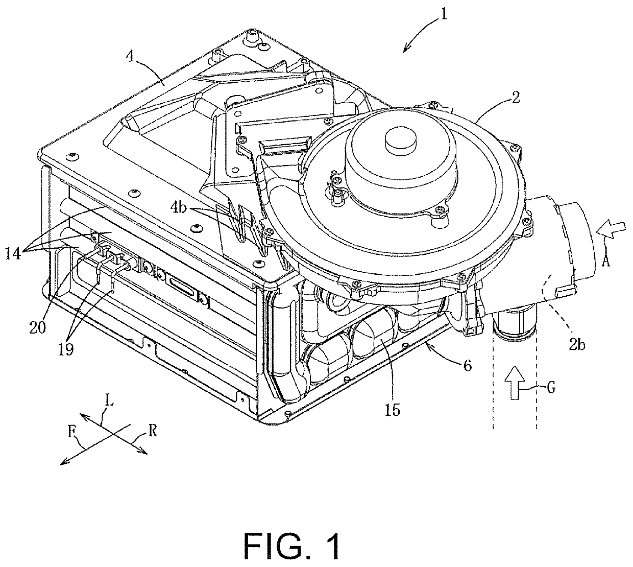
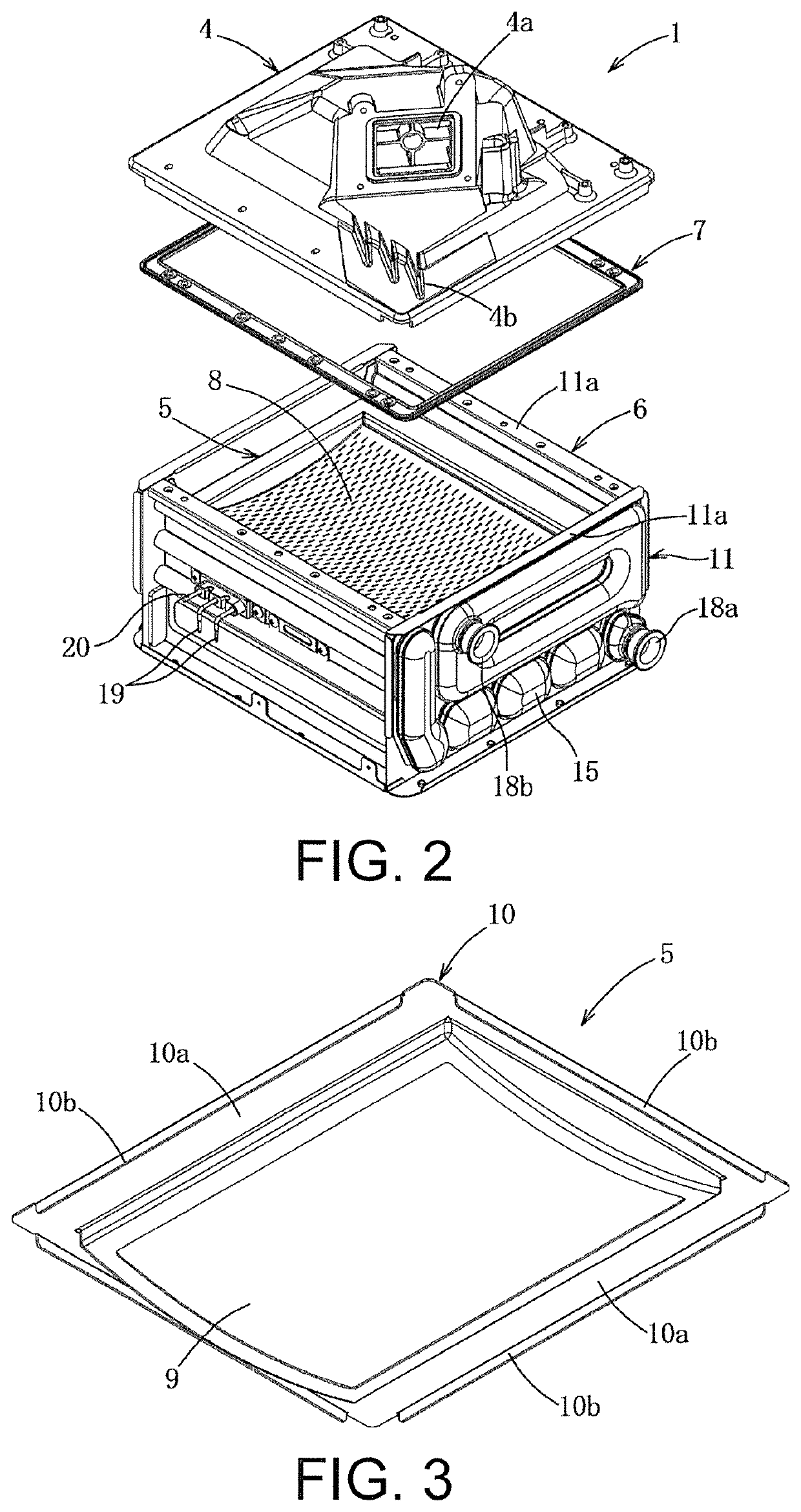
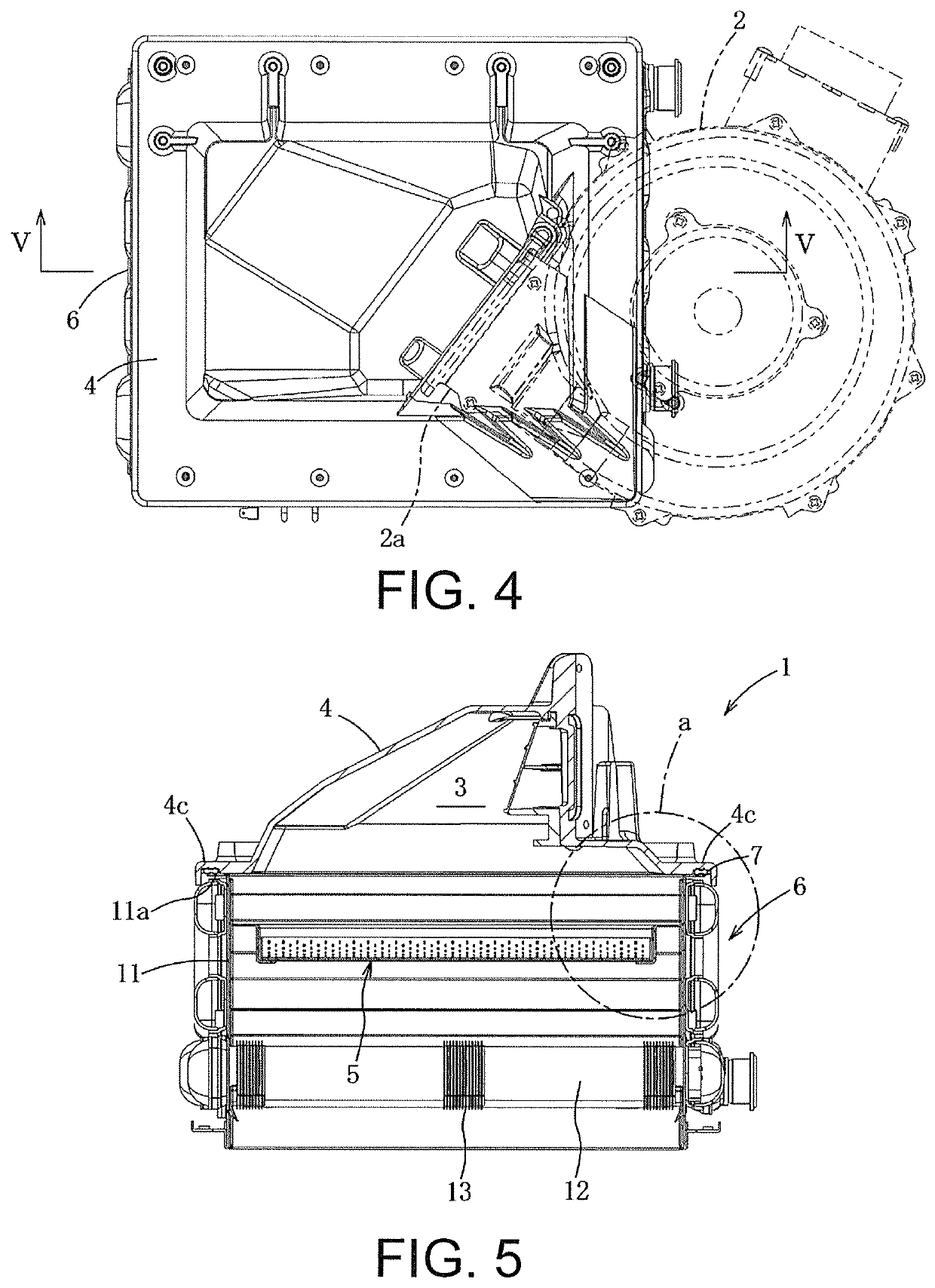
[0032]As shown in FIGS. 1 to 7, an all primary type inverse combustion type water heating apparatus 1 includes a fan 2 which supplies combustion air, a chamber case 4 in which a chamber 3 is formed, a inverse combustion type burner 5 set below the chamber case 4, a sensible heat recovering heat exchanger 6 set below the chamber case 4, and an air-fuel mixture sealing member 7, and the like. Further, F, L, and R in FIG. 1 will be described as the front side, the left side, and the right side.

[0033]The fan 2 is configured with, for example, a turbo fan and set on the side above the chamber case 4, and a blowout port 2a of the fan 2 is connected to a fan connection port 4a of the chamber case 4. The chamber case 4 is formed of an aluminum alloy and has a chamber 3 in which an air-fuel mixture is formed and the fan connection port 4a at a top portion thereof. A venturi 2b whic...


PUM

PropertyMeasurementUnit
degree of freedomaaaaaaaaaa
heat resistanceaaaaaaaaaa

Abstract

To provide a water heating apparatus which has a inverse combustion type burner installed within a case for a heat exchanger so as to cause heat to be transferred from an outer peripheral flange of the burner to the heat exchanger case. This water heating apparatus is provided with: a fan for supplying combustion air; a chamber case which is connected to the fan and which has set therein a chamber where an air-fuel mixture is formed; a inverse combustion type burner for combusting the air-fuel mixture supplied from the chamber; a heat exchanger in which combustion gas generated by the burner is introduced into a case where water is heated; and sealing member which is installed between a peripheral flange of the chamber case and a peripheral flange of the case, wherein the burner is set inside the case, and an outer peripheral flange of the burner is anchored to an inner wall surface of the case.

Description

BACKGROUNDTechnical Field[0001]The disclosure relates to a inverse combustion type water heating apparatus and relates to an apparatus in which an amount of heat transferred from a burner to a chamber case and a mixed gas sealing member is greatly reduced by setting the burner in a case of a heat exchanger and radiating heat from the burner to the case.Description of Related Art[0002]As shown in FIGS. 12 and 13, a conventional all primary type inverse combustion type water heating apparatus 100 includes a fan (not shown) which supplies combustion air, a chamber case 101 connected to the fan to form an air-fuel mixture in a chamber 101a inside the chamber case 101, a mixed gas sealing member 102 mounted in a sealing member groove 101c of a flange part 101b of the chamber case 101, a inverse combustion type burner 103 which burns the air-fuel mixture supplied from the chamber 101a, a heat exchanger 105 to which a combustion gas generated in the burner 103 is supplied to heat water, an...

Claims


Application Information

Patent Timeline
Patent Type & Authority Applications(United States)
IPC IPC(8): F24H1/10F23D14/02F24H1/00B23K1/00
CPCF23D2203/102F23D14/02B23K1/0012F23D2212/103F23D2214/00F24H1/0036F24H1/107F23D14/78F24H1/14F24H9/18F23L5/02Y02E20/30F23D14/145Y02B30/00F24H9/1832
Inventor MIURA, KEIICHI
Owner NORITZ CORP
Why Eureka
Try Eureka