
Dynamic intervertebral spacer implant

a spacer and intervertebral technology, applied in the field of intervertebral spacer implants, can solve the problems of increasing the apparent stress experienced by both the implant and the vertebrae, reducing the overall stiffness of the spacer, spinal stenosis and neurological complications,

Active Publication Date: 2020-03-12
ADDITIVE IMPLANTS INC
View PDF0 Cites 4 Cited by
  • Summary
  • Abstract
  • Description
  • Claims
  • Application Information

AI Technical Summary

Benefits of technology

The technology described in this patent aims to improve the performance of dental implants by addressing issues such as difficulty in preparing the end plate, expulsion of the implant, bone resorption, and lack of bone graft incorporation. The solutions provided by this technology include improved bone graft stimulation, reduced subsidence, and better visualization during dental procedures.

Problems solved by technology

Lastly, having dynamic elements reduces the overall stiffness of the spacer and allows the bone graft material packed within it to carry part of the load that is being transferred from one adjacent vertebral body to the vertebral body on the opposite side of the spacer.
Intervertebral disc pathology can result in the absence of physiological loading of vertebral end plates resulting in instability or degenerative changes over time, which may lead to spinal stenosis and neurological complications.
The seating of threaded cylindrical implants may also compromise biomechanical integrity by reducing the area in which to distribute mechanical forces, thus increasing the apparent stress experienced by both the implant and vertebrae.
Further, a substantial uncontrolled risk of implant subsidence (defined as sinking or settling) into the softer cancellous bone of the vertebral body may arise from such improper seating.
Even open ring-shaped cage or spacer implant systems, generally shaped to mimic the anatomical contour of the vertebral body, lack the ability to complement specific stiffness of the patient's bone.
Such allograft bone material restricts the usable size and shape of the resultant implant.
Therefore, these allograft cages may not be of a sufficient size to contact the strong cortical bone, the uncinate process, or apophyseal rim of the vertebral endplate.
These size-limited implant systems may also poorly accommodate related instrumentation such as drivers, reamers, distractors, and the like.
For example, these implant systems may lack sufficient structural integrity to withstand repeated impact and may fracture during implantation.
Further, other traditional non-allograft ring-shaped cage systems may be size-limited due to various and complex supplemental implant instrumentation, which may obstruct the disc space while requiring greater exposure of the operative field.
These supplemental implant instrumentation systems also generally increase the instrument load on the surgeon.
Traditional interbody spinal implants generally do not seat properly on the preferred structural bone located near the apophyseal rim of the vertebral body, which is primarily composed of preferred dense subchondral bone.
In the process of aggressive end-plate removal, however, the end-plates are typically destroyed.
Such destruction means that the load-bearing implant is pressed against soft cancellous bone increasing the risk of implant subsidence.
The end-plates are concave; hence, if a flat implant is used, the interface will not be well matched and the implant may not be very stable.
Even if a convex implant is used, it is very difficult to match the implant geometry with the end-plate geometry, as the end-plate geometry varies from patient-to-patient and on the extent of disease.
This method also violates the structure.
Both options can create localized stress risers in the end-plates, increasing the chances of subsidence.
The challenge of preventing implant expulsion is especially acute for PEEK implants, because the surface texture of PEEK is very smooth and slippery, with reduced purchase on the adjacent vertebrae.
Subsidence of the implant is a complex issue and has been attributed to many factors.
These design restrictions do not leave much room for filling the bone graft material into cortical bone implants.
The exposure-driven limitations on implant size narrow the room left inside the implant geometry for bone grafting even for metal implants.
In many cases, the typical interbody fusion implant is not able to incorporate with the vertebral bone, even years after implantation.
Such inability persists despite the use of a variety of different materials to construct the implants.
Stiff, typically metallic, implants stress shield the bone graft and do not supports its transformation into living bone.
For implants made of metal, the metal limits adequate radiographic visualization of the bone graft.
Hence it can be difficult to assess fusion, if it is intended to take place.
Metal implants are dense and inhibit the assessment of boney fusion via x-ray techniques.
In addition, they can create significant artifacts when utilizing MRI or CT scans to post-operatively visualize the implant / bone interfaces.

Method used


Image

  • Dynamic intervertebral spacer implant
  • Dynamic intervertebral spacer implant
  • Dynamic intervertebral spacer implant

Examples


Embodiment Construction

[0051]Exemplary embodiments of the technology will be best understood by reference to the drawings, wherein like parts are designated by like numerals throughout. It will be readily understood that the components of the technology, as generally described and illustrated in the figures herein, could be arranged and designed in a wide variety of different configurations. Thus, the following more detailed description of the embodiments of the apparatus, system, and method is not intended to limit the scope of the invention, as claimed, but is merely representative of exemplary embodiments of the technology.

[0052]The phrases “connected to,”“coupled to” and “in communication with” refer to any form of interaction between two or more entities, including mechanical, electrical, magnetic, electromagnetic, fluid, and thermal interaction. Two components may be functionally coupled to each other even though they are not in direct contact with each other. The term “abutting” refers to items tha...


PUM


Abstract

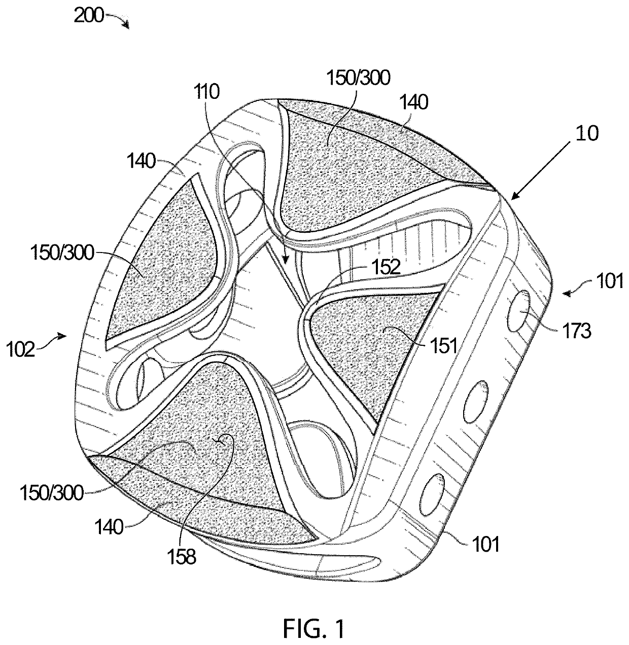
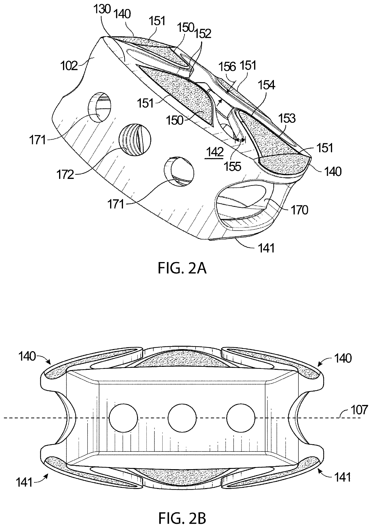
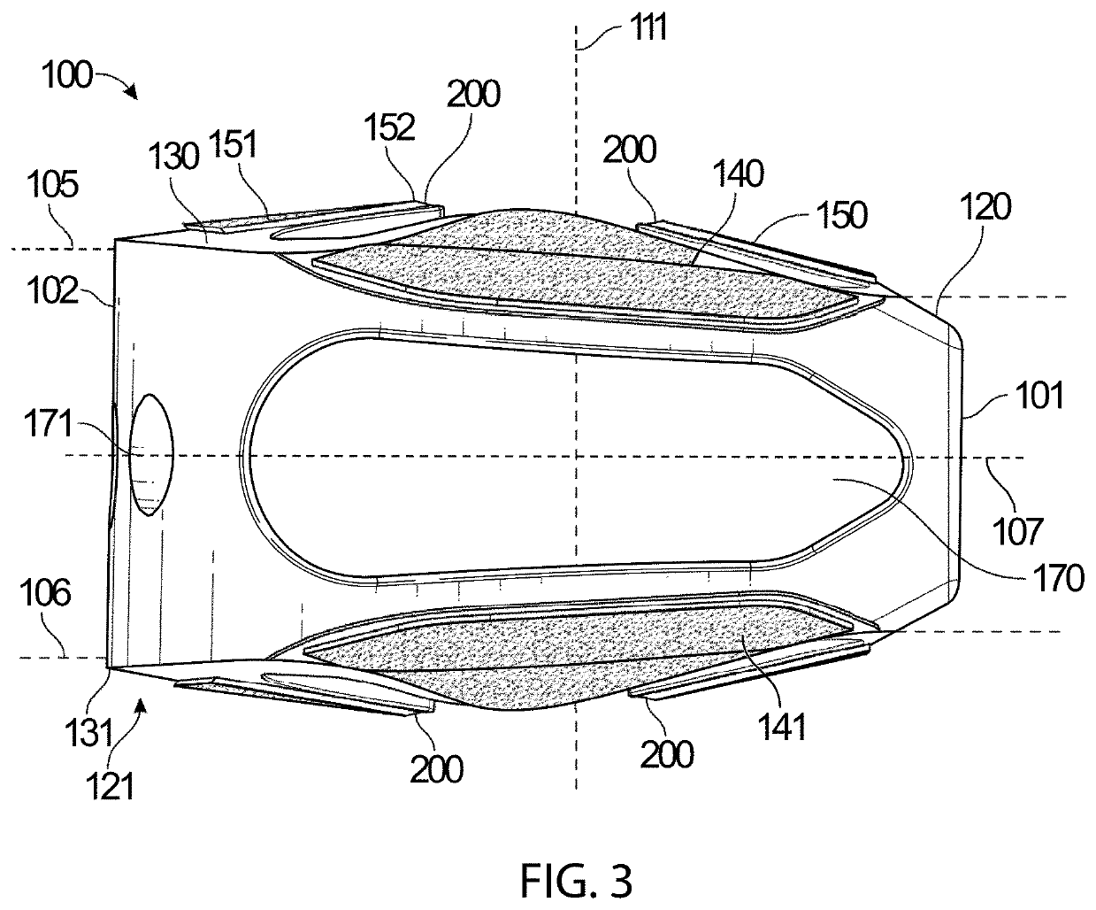
Intervertebral spacer implants with dynamic load spreading features responsive to external loads and having attachment mechanisms. The dynamic load spreading features having a native state and a loaded state, which complements vertebral end plate geometry and disperses load to the epiphyseal rim.

Description

CROSS-REFERENCE TO RELATED APPLICATIONS[0001]This application is a continuation-in-part of:[0002]U.S. patent application Ser. No. 16 / 383,142, filed Apr. 12, 2019, entitled DYNAMIC INTERVERTEBRAL SPACER IMPLANT, Attorney's docket no. INT-1 CON1, which is pending.[0003]U.S. patent application Ser. No. 16 / 383,142 is a continuation of:[0004]U.S. patent application Ser. No. 16 / 125,640, filed Sep. 7, 2018, entitled DYNAMIC INTERVERTEBRAL SPACER IMPLANT, Attorney's docket no. INT-1, which issued as U.S. Pat. No. 10,299,938 on May 28, 2019.[0005]The foregoing are incorporated herein by reference as though set forth in their entirety.TECHNICAL FIELD[0006]The present technology relates to intervertebral spacer implants. More specifically, the present technology relates to spinal interbody fusion implants (spacers) having dynamic elements on at least one side of the implant body. Implants with dynamic or flexible elements allow the spreading of intervertebral load across the end plate of the v...

Claims


Application Information

Patent Timeline
IPC IPC(8): A61F2/44
CPCA61F2002/30772A61F2/442A61F2002/30265A61F2002/30112A61F2002/30324A61F2002/30593A61F2002/30622A61F2002/30069A61F2/447A61F2002/4629A61F2002/30179A61F2/4455
Inventor EHTESHAMI, JOHN R.ZOGHI, MAHYAR
Owner ADDITIVE IMPLANTS INC
Learn More