Igniter for gas turbine engine

a gas turbine engine and ignitor technology, applied in the field of gas turbine engines, can solve the problems of reducing the reliability of spark plugs, for example, drawbacks of spark plugs,

Inactive Publication Date: 2020-03-12
PRATT & WHITNEY CANADA CORP
View PDF0 Cites 3 Cited by
  • Summary
  • Abstract
  • Description
  • Claims
  • Application Information

AI Technical Summary

Problems solved by technology

However, spark plugs for example have drawbacks.
For instance, the spark plugs have been known to achieve less than full reliabi

Method used


Image

  • Igniter for gas turbine engine
  • Igniter for gas turbine engine
  • Igniter for gas turbine engine

Examples


Embodiment Construction

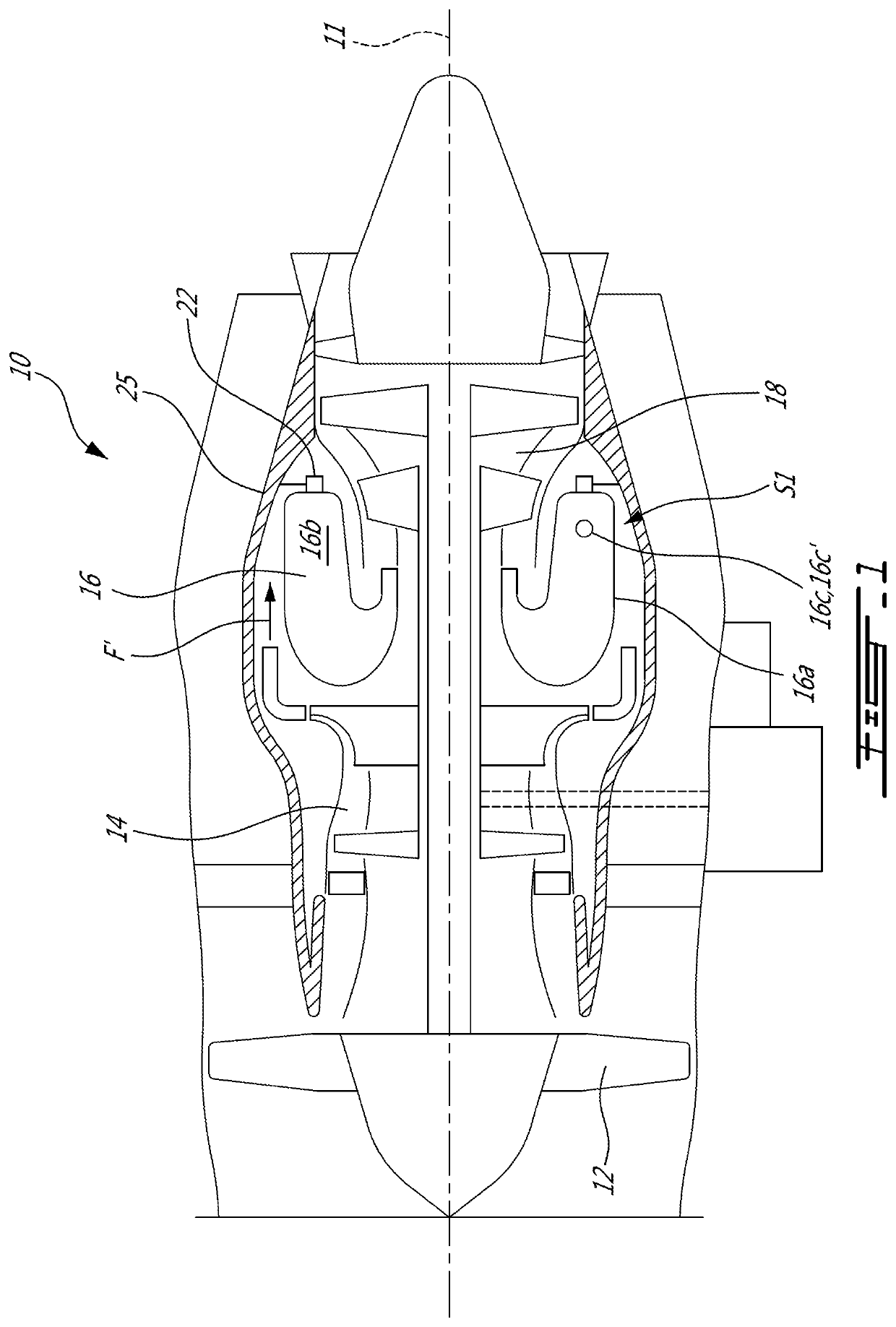
[0035]FIG. 1 illustrates a gas turbine engine 10 of a type preferably provided for use in subsonic flight, generally comprising in serial flow communication a fan 12 through which ambient air is propelled, a compressor section 14 for pressurizing the air, a combustor 16 in which the compressed air is mixed with fuel and ignited for generating an annular stream of hot combustion gases, and a turbine section 18 for extracting energy from the combustion gases. The fan 12, the compressor section 14, and the turbine section 18 rotate about a central axis 11.

[0036]In this embodiment, the gas turbine engine includes an engine casing 25 that is disposed radially outwardly of the combustor 16 relative to the central axis 11. The combustor 16 has a combustor liner 16a that encloses a combustion chamber 16b. The combustor liner 16a can form part of the engine casing 25 and not rotate with the rotors. The combustor liner 16a defines at least one igniter liner aperture 16c for receiving at least...


PUM


Abstract

There is disclosed an igniter for a gas turbine engine including: a base, a glow plug heater rod extending from the base along an axis and terminating in a rod end, a sleeve extending circumferentially around the glow plug heater rod along at least a portion of a length of the glow plug heater rod, the igniter having a ventilation path extending from an inlet to an outlet, the inlet fluidly connectable to a spacing located between a casing and a combustor liner of the gas turbine engine, the outlet extending circumferentially around the glow plug heater rod and oriented axially relative to the axis, the outlet fluidly connectable to a combustion chamber of the gas turbine engine delimited by the combustor liner.

Description

TECHNICAL FIELD[0001]The application relates generally to gas turbine engines and, more particularly, to igniters used for gas turbine engines.BACKGROUND OF THE ART[0002]Spark plugs are commonly used to ignite a mixture of air and fuel in a combustor of gas turbine engines. However, spark plugs for example have drawbacks. For instance, the spark plugs have been known to achieve less than full reliability in conditions such as when wet by exposure to condensation or washing fluid, or when the fuel and the engine are very cold. Cost is also a factor. There is always room for improvement.SUMMARY[0003]In one aspect, there is provided an igniter for a gas turbine engine comprising: a base, a glow plug heater rod extending from the base along an axis and terminating in a rod end, a sleeve extending circumferentially around the glow plug heater rod along at least a portion of a length of the glow plug heater rod, the igniter having a ventilation path extending from an inlet to an outlet, t...

Claims


Application Information

Patent Timeline
IPC IPC(8): F02C7/266F23R3/42
CPCF02C7/266F05D2240/90F23R3/42F23R3/002F23R3/18F23R2900/00015
Inventor FREER, RICHARDMCCALDON, KIANHU, TIN-CHEUNG JOHNBOUSQUET, MICHELFORTIN, ANDRÉ
Owner PRATT & WHITNEY CANADA CORP
Why Eureka
Try Eureka